Get Started
To get started with the Gizmo, there are some common steps you'll need to take to get up and running. This section provides you with a walk-through on how to get up and running with the software you'll need to use to install as well as how to reprogram the System Processor firmware.
A deeper look at the Gizmo
Lets start out with a deeper look at the Gizmo itself. Here's a picture of what the circuit board looks like with everything installed:
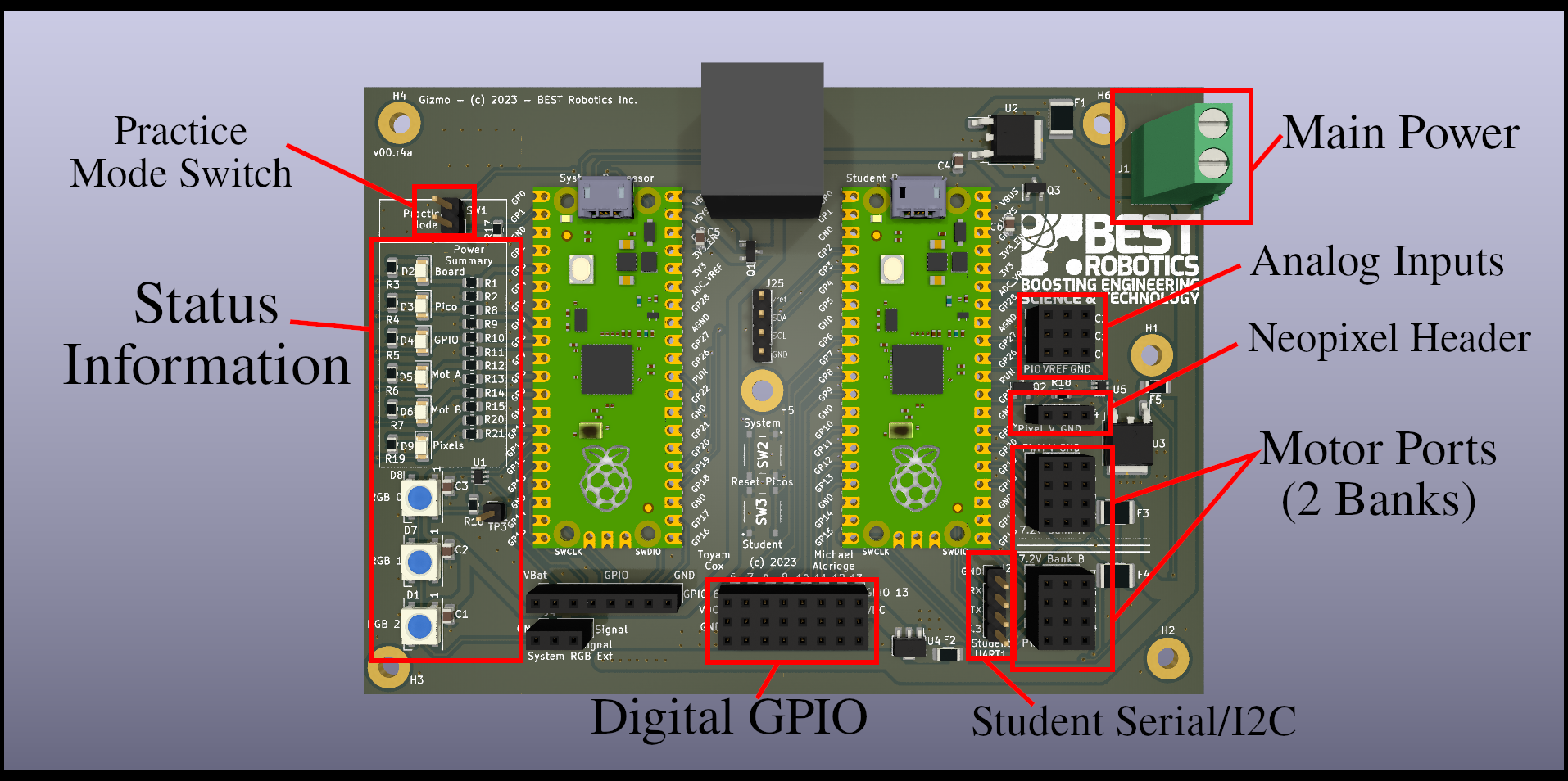
In the center of the board you can see the two Raspberry Pi Pico modules while run the system code and user code (your code). These devices are "socketed" meaning that they are not permanently attached to the board. This enables you to replace them if they become damaged, and to swap them out in order to isolate problems.
note
Note that the picture above is for hardware revision v00.r4b. You may have a different hardware revision with components in different places. If that's the case, pick your version from the table of contents to get more specific information.
The different components are called out on the board. Lets go through each section that's identified:
Main Power Connector
This screw terminal block provides the main power connection to the board. The positive terminal is the one towards the bottom of the board. When installing wires, make sure that you don't have any exposed metal sticking out of the connector, and tighten the screws until they are finger tight. You should be able to tug gently on the wires and not pull them free.
Analog Inputs
The Gizmo is equipped with 3 analog inputs. Analog inputs are able to read a range of values which fall into a defined range. The Analog inputs on the Gizmo are read with 12-bit precision, which means there are over 4000 discrete steps in its range. You can use an analog input in combination with a potentiometer to provide a very precise reference of the position of a component. If you use this precise feedback to drive a motor, you can create a custom high-power servo to drive components of your machine to specific places and maintain that position.
NeoPixel Header
NeoPixels are programmable, chain-able LED components that you can use to display information on your robot, make status information visible remotely, or just look cool.
info
Be aware that NeoPixel is a trade name for programmable integrated light sources popularized by AdaFruit. The drivers on the Gizmo are designed to support WorldSemi WS2812 Integrated Light Sources.
warning
In theory you can continue chaining NeoPixels end to end indefinitely, but putting too many together can draw too much power. The Gizmo is protected by self-resetting circuit breakers, but its still not good to add too many LEDs. As a rule of thumb, we design the header to support about 35 LEDs being powered on at any given time. You can have more than this connected, but don't turn them all on at once!
Motor Ports
Motor ports are able to supply high current power directly from the main power connector to larger peripherals, usually motors or servos. These ports provide power, access to a General Purpose Input/Output (GPIO) line and a ground connection. The ports are split into two groups to help you visually identify ports 1-4 and 5-8. Each group of 4 ports has an independent power supply limited to 4 Amps of continuous current draw.
Student Serial / I2C
For more advanced peripherals, this port provides access to a power connection and two GPIO lines. These lines are connected to special hardware on the Raspberry Pi Pico to enable either high-speed serial data or I2C bus communications. You can only use one communications protocol at once through this port.
Digital GPIO
The Digital GPIO ports provide access to 8 I/O lines that can be used for connecting to limit switches, IR sensors, or other input devices that allow you to sense the environment. Each I/O line has a 3.3v reference voltage and ground supplied. These lines are connected to the I/O lines on the Pico directly, so its important that you don't feed power into them from any other ports as this could damage the Pico.
Status Information
On the far left-hand side of the board is a vertical row of status lights. There are 6 lights which are specific colors and 3 lights which change colors. The fixed-color lights show you the status of the power systems on the board. If a light has gone out, that means that a corresponding system has lost power because the protection circuit tripped. Remove the main power supply by either turning off your power switch or removing the battery and inspect your wiring for short circuits (places where two wires touch directly without insulation) or components that are stalled out such as a motor that can't turn because something has jammed.
The 3 color changing lights provide information about key components of the Gizmo system. In order top to bottom:
-
The top-most light provides information about the wireless communications link. If the light is red it means that the Gizmo cannot find your driver's console. A yellow light means that the connection has been established, but the Gizmo hasn't yet started receiving information from the gamepad and field management system, and a green light lets you know you're good to go.
-
The middle light provides indication of what field and color you have been assigned. The light will blink the number and display the color. For example, if you were assigned to the red position of field 1, the middle LED would blink a single red pulse once per second. If you were on the blue position of field 3, you'd see 3 fast pulses of blue light once per second.
-
The bottom light provides an indication of battery voltage using a traffic light coloring system. If the light is green you have a freshly charged battery at max voltage. As the light changes color closer to red you should consider changing your battery. Its normal during use for this light to change colors as various components use power. The status of the light when nothing else is using power is the important indicator.