Welcome to Gizmo!
Welcome to the Gizmo robotics platform. This open source hardware and software ecosystem will enable you to build advanced mechatronics systems. You don't need to be an expert to build something impressive!
This guide will walk you through what the various components of the Gizmo ecosystem are, how to use them, and a getting started experience in a variety of languages. While we recommend you sit down and read all of the getting started information as a single unit, each section can be consulted standalone for quick reference.
Document Conventions
Throughout this manual we'll use certain document conventions to signal different information.
note
This is a note, it has information in it that may give you more context or help you understand a concept better.
warning
This is a warning, and as you might expect, it warns you from something you probably don't want to happen.
tip
This is a tip. It contains advanced information or a quicker way of doing things, but may not be as easy to grasp as the alternatives presented around it.
This is a code block.  We'll use these when we want to show you
programs or source code.  In those cases, the code will have colors to
make it easier to read.
This is a command example. You can tell its a command because we've put a $ and its shown in a special monospace font to match the one in your PowerShell or terminal window. Do not type the $, it is shown only to make clear the beginning of the command.
$ .\gizmo.exe
This is a menu reference. We'll use this formatting to show you a path through a context menu to a particular option. Each item between the '>' characters is one item in the menu that you can mouse over to access the next layer. The final item is the one you click on.
File > Options > Weather Control > Rain > Material > Cats/Dogs
Learning Resources
In this section we'll dive into what the Gizmo is, how it works, and how it was built. You'll find links to further reading, video resources, and discussions into how the entire Gizmo platform works together.
You don't have to understand or even read this section to be able to use the Gizmo, but it will help you gain an understanding of how all the parts fit together and the design rational that led to the development of the Gizmo platform.
What is the Gizmo?
The Gizmo refers to a platform, a software tool, and a physical hardware device that goes on a robot. The when we refer to "The Gizmo" in this guide, we're referring to the physical hardware device unless otherwise specified. If we need to refer to the software tool, you'll see those references formatted like this with the unique font and coloring to indicate we're talking about the Gizmo software tool.
The Gizmo is a carrier board that accepts two Raspberry Pi Pico micro-controllers. These micro-controllers, referred to as the System Processor on the left and the User Processor on the right make up a programmable controller that can be customized.
What is a Micro-controller?
You now know that the Gizmo contains two different micro-controllers, but what is a micro-controller? In short, a micro-controller is a small programmable device not unlike a primitive computer. In fact, micro-controllers are computers, just very simple ones. The computer you use to browse the web, write documents, and watch media on operates on the same principles as a micro-controller, just much faster and with more capability. The micro-controllers used on the Gizmo are made by the Raspberry Pi foundation and contain integrated memory, processors, and peripherals that let them communicate with other devices such as motor controllers, limit switches, wireless radios and more.
If you want to learn more about micro-controllers, check out the Wikipedia page and remember to check the listed sources at the bottom of the page for further reading!
What is a Carrier Board?
Earlier, we referred to the Gizmo as a carrier board. As the name implies it's a board that carries. The board referred to in this case is a fiberglass circuit board that contains a printed electronic circuit. The fiberglass is covered in various layers to build up the circuit, and part of that circuit includes the two processors from above. These processors are "carried" by the board and it provides support components such as connectors, power supplies, and mounting holes.
The circuit board on the Gizmo is colored green with a dye called a "solder mask" which makes it easier to assemble and protects the board from abrasive damage. Be careful when handling a circuit board outside its case because this layer is very thin and can be scratched off by sharp objects!
To learn more about printed circuit boards, this Wikipedia Article gives a good overview, and this episode of Branch Education on YouTube gives a walk through of how PCBs work by looking at the parts that make up a cellphone. The Gizmo is built using the same technologies.
System vs User Processor
There are two processors on the board, both designed by the Raspberry Pi foundation. This organization develops advanced microcontrollers and Single Board Computers (SBCs) that are popular in the education, hobbyist, and industry. The Gizmo uses a two different Raspberry Pi Pico devices. The system processor is a Pico WH which contains a built in wireless radio assembly, and the user processor is a Pico H which uses the same components as the WH version, but does not include a wireless radio.
We use two processors to split up the responsibilities that are handled in controlling a robot. The system processor runs code developed by the Gizmo team and it handles communicating with the driver's console, the field management system, and supervising the user processor. The system processor is also able to reboot the user processor if it detects that the user processor has frozen, or if a programming error causes it to become "stuck" in a loop.
The user processor is where code that you write will go. It has access to motor ports, sensor ports, analog input ports, and a dedicated port for connecting programmable LEDs to to display information, provide feedback about automatic systems, or just look cool. The user processor communicates with the system processor using I2C.
Architecture
The Gizmo platform is comprised of several different components. In this section we'll look at the architecture of the software, the hardware, and the interfaces between different components.
You are not required to understand the architecture to be able to use the Gizmo platform. This will not be on the test.
Overall System Architecture
The overall architecture of the Gizmo system composes a control point, the Gizmo itself, and anything hooked up to it. This can be broadly visualized with the diagram below:
Gizmo Hardware Architecture
The hardware architecture is comprised of 2 processors, an I2C link between them. Here's a block diagram of how it all works.
The system processor is implemented as a peripheral device that the user processor controls. This allows the user code to be the root node on the I2C bus which dramatically simplies the implementation. The System Processor also supervises a number of different devices on the board including voltage supply rails, battery input voltage, and when the last time the User Processor asked for data was.
Gizmo Software Architecture
The command line gizmo tool is a "multi-call binary" meaning that it can do different things depending on the options you start it up with. You can think of it as a bunch of different programs all contained in the same file which makes it easier to distribute. The same exact gizmo tool is what runs on the Driver's Stations and the FMS. While we make every effort to make compatible updates, in general you'll want to run the same version of the Gizmo utilities everywhere. We note explicitly when backwards compatibility cannot be maintained, so check the patch notes.
Direct Connect
Speaking in terms of time connected, most Gizmos will spend most of their time in what is called "Direct Connect" mode, which forms a direct point-to-point link between the Driver's Station and the Gizmo System Processor. This looks like this visually:
The control is passed from the gamepad to the Driver's Station via USB, then via wireless link to the Gizmo System Processor, then via I2C to the user processor where these values are consumed by user programs to control a robot.
Field Radio
During a competition, it is imperative that a solid link be maintained between the Gizmo and the Driver's Station. The weak part of this chain is the wireless conection, so to ensure a solid connection, we replace the Driver Station's internal radio with a substantially more powerful external radio wth external antennas. This also ensures that each team is equally affected by any interference, since the central radio talks to all robots on a given field. One field radio per field is required.
The FMS does not process or interact with the control data, it only provides a different means of transfering this control stream from the DS to the Gizmo. Visually, this is the path:
The FMS maintains an isolated data-path for each Gizmo/DS pair, and ensures that no robot can interfere with another's control stream. This is why the FMS needs to know where each team is located, so that it can provision the correct access onto the specific Field Box port going to that team.
Observability
Gizmo boards pass statistics information back to the driver's station, which in turn shares them with the FMS. The Gizmo board also reports some metadata information related to things that can prevent the system from working directly to both the Driver's Station and the FMS.
You can use this information to get a better understanding of what's going on with your field and Gizmos. Here are some example questions you can answer using this data:
- Are all Gizmos connected?
- Is there persistent interference?
- Did any team experience a disconnect?
- What is the battery voltage on all connected Gizmos?
This information is ingested by the metrics module and made available over HTTP as an OpenMetrics compatible metrics stream. Example Prometheus and Grafana configurations are available in the Gizmo repository.
Network
warning
This learn page is SIGNIFICANTLY more technical than any of the others. You are not expected to understand this, and it represents an extremely deep level of knowledge in systems and network engineering. If this kind of stuff interests you, consider a career in network engineering!
The Gizmo platform relies on a lot of IP communications to move data from one place to another. This data comprises location information for robot assignments, control data for various systems, and status information reported back to centralized logging and metrics collection systems. In order to maintain a uniform approach, all of these systems communicate over one or more IP networks.
During field initializations, a special local subnet is used to communicate between the FMS and the Scoring Box which provides core IP services to the network. This is done since during setup the layer 2 network topology will be changed, and the normal IP addresses the system would use are not yet available. Once the core FMS network is up, field boxes, the FMS server, and scoring boxes receive IPs in the 100.64.0.0/24 subnet. While this subnet is not intended for local assignment, instead being part of the CG-NAT allocation (RFC6598). We select this range and the adjacent subnet for bootstrapping (100.64.1.0/24) due to the extremely small chance in a collission between this range and the range in a host venue, which would render normal NAT services impossible to deliver. There is no risk to sitting this range behind an external CGN as the intermediate NAT will prevent each side from seeing the conflicting range.
Gizmo communications happen on networks which include the team number. The team numbers all reside within the RFC1918 space in the 10/8 Class A block. This space was chosen to allow for up to 9999 teams to be identified in a single network without additional considerations. Future work would include migrating the Gizmo network to IPv6 space in order to permit an even higher limit to number allocations.
Team subnets are allocated by taking the team number, padding to 4 digits, then splitting the first and second 2-digit groups into the second and third octets of the address. For example, team number 4 would be represented as 0004, then assigned IP space in 10.0.4.0/24. Note that duplicate zeros are collapsed prior to allocation. While technically not necessary, this normalization makes addresses easier to parse and reason about. Lets look at another example. Team number 1729 is already 4 digits in length, so we partition the number and allocate 10.17.29.0/24 for this team's use.
Wireless Networks
The Gizmo is designed to function as part of a mobile robotics platform, and as such needs to support wireless communications. While a variety of wireless standards exist, we use 802.11n wireless networking in the 2.4Ghz channel space. This ensures a good balance between range, overhead, and interworking with other wireless users.
By operating according to the 802.11n standard we support the most permissive interworking profile, and can down-clock to support any lower mode, ensuring that the Gizmo poses no risk to any other nearby fixed or mobile networks following North American standards. Interworking profiles are how this is achieved, and the Gizmo supports the highest profiles currently available for the 2.4Ghz bands.
While the flexibility of the 802.11n standard allows the use of any SSID and security combination, for consistency the Gizmo makes use of specific patterns. Since no human needs to join the point-to-point control network the SSID is formatted as a 64 character hexadecimal sequence. This sequence is randomly generated and is the maximum length that SSIDs are permitted to be. Similarly, WPA2-PSK authentication with TKIP encryption is used to secure the channel against unauthorized users. The gizmo utilities generate 64 character random hexadecimal strings to use for these keys.
FMS Network
Based on the information above, we can now fully detail the FMS network. The network is comprised of 2 broad components. First, the internal network on which the FMS workstation, the scoring box, and all field boxes reside is formed. This network resides in the 100.64.0.0/24 space, and is the only network from which certain control actions can be taken. It operates on VLAN ID 1 using standard 802.1q tagging for ports facing internal devices.
Team networks are assigned to VLANs with numerically increasing IDs starting at 500. While this technically limits the number of teams that could compete in a single event to just 3,596 it is considered an acceptable tradeoff given that no venue exists which can comfortably host that many teams. Prior to each match, the team location mapping is consulted to determine which field and quadrant each team will be assigned to, and the relevant networks are made available on those radios and access ports. This sophisticated automation is managed by the FMS workstation, and is completely passive once changes are synced.
network address management
All team addresses are statically assigned and are at fixed
locations. The Driver's Station will always be at .2, and the
Gizmo will always be at .3.
Why do we do this? Most network you interact with are configured dynamically using DHCP (literally 'Dynamic Host Configuration Protocol'). DHCP is great for networks that you're willing to wait a few seconds for connectivity. In the case of a robotics platform, this delay is unacceptable and we pre-calculate all addresses to allow instantaneous assignment on boot. This has the practical upshot of reducing connection times from ~10 seconds down to about ~4 seconds in the worst case, and often much faster than that.
Driver's Station
The Driver's Station is a component that provides the termination point of the USB data stream from the gamepad and is the point at which control messages are inserted to the UDP data stream. The driver's station allows the platform to be self contained by providing all of the services that the full fledged FMS does when not connected.
The Driver's Station is implemented as a command that is part of the Gizmo tool. Because the Driver's Station is highly specific to the underlying Linux APIs that interact with the network stack, it is only compiled for the Linux architecture. This is why if you download the gizmo tool on macOS or Windows, you won't have an option to run the ds commands.
Internal to the driver's station system image, there are several processes that are running. We'll look at each one in detail.
hostapd
This process manages the wireless radio. Its considered a Swiss Army Knife of radio management, and is what powers most commercial access points under the hood. On the driver's station, it takes care of managing the point-to-point network that gets created when not using a field management system. Its managed and supervised by other parts of the system image and is stopped when the FMS is connected, which has the side effect of shutting down the local radio in the driver's station. This is important to reduce interference by having as few transmitting radios powered on as possible.
gizmo-ds
This is the main driver's station process. It is the result of the gizmo ds run command. It takes care of polling the gamepad, connecting to the Field Management System (FMS) and providing localized field services when the FMS is not available, such as during a practice scenario or during development of your machine.
gizmo-link
The gizmo ds linkmon process runs to supervise the network. On the driver's station, the wireless and wired interfaces are part of a bridge device. You can learn more about bridge devices in the Kernel Wiki. The practical upshot of this is that from the perspective of software on the driver's station the connection medium (Ethernet or WiFi) doesn't actually matter, only the address matters and there is exactly one of those since its held by the bridge.
The linkmon process also watches what's going on with the Ethernet interface and if it sees the link status change, it restarts gizmo-ds so that any control streams are forcibly re-established.
gizmo-config
The gizmo ds config-server process provides a serial configuration server that is part of the pairing process with the Gizmo. This enables the driver's station to provide its gsscfg.json to any connected Gizmo that's in binding mode. The config-server checks every 5 seconds to see if a USB device was connected that identifies itself as being a Raspberry Pi Pico and is pretending to be a serial port. If its a serial port, the config-server opens the port and waits to see if it receives the string GIZMO_REQUEST_CONFIG. Once this string is received, the configuration data is sent back across the serial link and the port is closed.
note
Actually before the port is closed, it has to be "drained". This is a limitation of the way that serial ports and specifically UARTs work, which means that we need to write data into the port and then wait until the port says its written the same number of bytes that were dumped into it, meaning that all data has been sent.
gizmo-logmon
The gizmo-logmon process is responsible for copying the log file to the HDMI port, so that you can plug in a monitor to see the log scroll in real-time. This is an advanced debugging feature, but may be useful for some users.
console
The console service is an advanced debugging feature that allows access to the running system on the driver's station. To access it, connect a monitor and keyboard and press ctrl + alt + f2. Keep in mind that the Gizmo DS boots from read-only storage, so changes you make while in the console won't be saved.
dnsmasq
While the Gizmo and the Driver's Station have statically defined addresses, not all devicse do. The dnsmasq service provides DHCP to devices connected to the Driver's Station's Ethernet port. This is useful to plug in a laptop and review the metrics data from the Driver's Station when not using the FMS.
Boot Time Configuration
All of the services we've talked about so far run as long-lived processes once the embedded operating system on the Driver's Station finishes initialization. During late-boot, however, there is a gizmo ds configure process that runs as a one-shot process which performs initialization and exits.
The configure process is responsible for several things. Primarily, it sets up all the services that are mentioned above, and it configures the network devices. These steps happen once per boot, and are what allows the driver's station system image to be completely identical for all machines with the only distinction being the gsscfg.json file. This file is read from the boot partition to setup all the other services.
The gsscfg.json file can be statically provisioned to the /boot directory, however this is not recommended. Just before gizmo ds configure runs, the autoconfiguration phase will occur. If the volume label is of the form GIZMOXXXX where XXXX is a number, the config file will be automatically generated using XXXX as the team number. This allows the images and contents of the micro SD cards to be completely identical, with the only distinction being the volume label, which makes mass-imaging cards more feasible.
Field Management System (FMS)
The Field Management System is, as the name would imply, a system that provides management services for one or more fields. These services include scheduling, orchestration of the field networks, collection of logs and metrics, and interfaces to consume and configure all of these features.
Why is there an FMS?
You might wonder why there's an FMS at all. After all, the Driver's Station provides a fine way of controlling a single Gizmo, so you should be able to just have a bunch of driver's stations all controlling a bunch of Gizmos, right?
Technically this works, but it comes with some major caveats.
First off, without a central coordinator its difficult to ensure that every user gets a fair slice of airtime to send and receive control information. If one user is consuming all the available time then that shows up as other Gizmos resetting, stuttering, or acting erratically due to an inconsistent control stream.
Second, the Driver's Station doesn't have a very good radio in it. Its perfectly fine for short range practice or limited use, but its not as powerful as a fixed radio with good antennas. Ideally, we'd want to have one of these more powerful radios per field to allow the machines on those fields to have the shortest possible connection path back to a powerful radio that fairly divides its transmit time amongst Gizmos that need it. Which Gizmos need it? To ensure the most fair scenarios in a competition, only machines that are associated with a currently active match should be operating wirelessly since this ensures that bandwidth isn't being spent on data that's not part of match.
To solve this coordination problem, we need a central component that manages this complexity. This component is the FMS and is comprised of hardware and software that work together to manage one or more fields.
What is the FMS?
The FMS is made up of 3 key components. Each of these components has a specific function to fill and works in concert with the others. These components are referred to as the FMS Workstation, the Scoring Box, and Field Boxes.
FMS Workstation
The FMS Workstation is a Linux computer that actually runs all the software. This software includes a suite of utilities that perform configuration and management utilities, and an observability stack that provides centralized management of logs and metrics.
The FMS Workstation can techncially be any Linux computer, but the Gizmo team peforms detailed testing and releases software images that target the Raspberry Pi 400/500 series, which is a convenient self contained computer with a dual monitor capability.
Scoring Box
The Scoring Box is a network device that resides at the Scoring Table with the FMS Workstation. The Scoring Box is just commodity network hardware, a Mikrotik hEX Lite. The Gizmo team recommends using the hEX Lite PoE version, since this allows the Scoring box to power all the Field Boxes remotely. The Scoring box hosts all the DHCP servers, DNS server, NAT services, and a host of other advanced network components to support interoperability between the Gizmo network and other networks which may be present at events.
note
If you are running a very large event, it is possible to make use of "Jumbo Mode" where your Scoring Box is replaced with a Mikrotik RB5009-PoE. This can be extended even further by using programmable trunk switches to achieve more fields than any venue in the US can hold. This is certainly an advanced use case, and if you think you need this, reach out to the Gizmo team for advice.
Field Boxes
Field Boxes are Mikrotik hAP ac3 devices that are associated with fields. Each field has exactly one field box, which means most users will only have one in total. The Field Box contains the dual-chain radios, as well as provides 4 Ethernet ports for driver's stations to plug into. The field boxes are powered ether locally or using passive PoE from the scoring box. In addition to the SSIDs used by the Gizmo devices, the Field Boxes also have 5Ghz facilities to broadcast a network suitable for scoring control, information transfer, or just general access for game related hardware that is independent of the wired network.
How did the Gizmo get built?
Like everything, the Gizmo had to be conceived of as an idea, designed, and then fabricated. This section will give you an overview of how the team behind the Gizmo designs the hardware, software, and arranges for these designs to turn into real physical devices.
Tools and Opinions
Keep in mind that the Gizmo team is largely composed of engineers with wildly varied professional careers. These are the tools that we use, and these are based on our opinions around support, capability, and ease of use. If you want to do something similar to the Gizmo, evaluate what your team knows how to use and select your tools accordingly. We largely run on top of Linux which influences our tool choices significantly.
The Gizmo also leverages a large amount of Open Source software and hardware tooling. This tooling is available for free for anyone to inspect, learn from, use, or build on top of to create some thing new. If this sounds interesting to you, learn more about Open Source here.
Across all our workflows, we make use a Distributed Version Control System (DVCS). Our DVCS of choice is called Git and is very popular across industry, education, and hobbyist markets. Using a DVCS allows our team to each contribute to different components of the system from our individual places of work be it at home, in an office, or even a coffee shop. Git tracks all the changes that we make to each portion of our systems, and to revert changes that we don't like. In order to collaborate, we make use of a hosted platform for Git called GitHub. Even the docs you're reading right now are hosted on GitHub for us to collaboratively edit, review, and publish as changes happen. If you want to look at all our different work-spaces (called "repositories" on GitHub), you can start from our organization page.
Hardware
The Gizmo is physically comprised of a circuit board and a case for that circuit board. We use different tools to design each part.
Printed Circuit Board
We design the Gizmo using an Electronic Design Automation suite called KiCAD. This software allows us to lay out our printed circuit boards, generate the files that our fabrication partners require, and automatically verify that our designs conform to certain rules. KiCAD is functionally similar to other Computer Aided Design (CAD) suites used for designing mechanical systems such as SolidWorks, AutoCAD, TinkerCAD or OnShape, just to name a few.
When designing a circuit board, its important to verify that not only the wires go where we expect, but also that we're observing any rules that are imposed by the company that manufactures our circuit boards. We're able to configure KiCAD to automatically check these Design Rules with Design Rule Checks (DRC). Design Rule Checks are just like spellcheck. We run our designs through both standard DRC workflows, as well as specific sets of rules that are provided by manufacturers that validate our designs can be built by their machines.
Case
We use a couple of different tools to design and fabricate cases, depending on the manufacturing technology that will be used to produce the case. Our standard 3d printed case is designed using Blender. Blender is an extremely powerful 3d modeling, VFX, rendering, and video workbench. Best of all, its Open Source! Blender allows us to make very fast changes to the design of the case and directly export a design into the file format used by most 3d printers.
Software
The Gizmo ecosystem is comprised of a number of different software components. There's firmware that gets loaded onto the System Processor on the Gizmo board, support libraries for all the languages that you can use to program your own code on the User Processor and software that has to run on a computer to orchestrate the data for multiple robots. This software is all broadly developed using the same workflows.
We start with a description of what the software should do, this can be a description written in English such as "the software should retrieve gamepad data and make that available to the user", or it can be a more machine oriented description such as this interface definition:
// JSController defines the interface that the control server expects
// to be able to serve
type JSController interface {
	GetState(string) (*gamepad.Values, error)
}
After we know what the software needs to do we usually write a really rough first draft of it that is functional, but isn't pretty. This rough draft will inform us as to whether the description is complete, and how the different parts need to fit together. After writing the rough draft, we'll circulate it amongst other developers to receive feedback and advice on how to change or improve the code. This is a crucial step that often catches errors in both design and implementation.
Incorporating the feedback as well as the better understanding we gained from the rough draft, we then revise our code to a more polished version. This may include refactoring code, creating new modules to encapsulate specific tasks, or scrapping the code and starting over if our initial assumptions weren't correct. What's important is that throughout this process we're creating checkpoints our work in Git (called 'commits'). These are specific changes that we write a message describing and can revert to later.
After we've reached a point where we're happy with the code, we need to release it and distribute it for people to use. Depending on the project, we have various ways to do this. For this gizmo tool itself, we use GitHub Actions to compile it for multiple operating systems and architectures, then compress these compiled artifacts for download directly to end users. For components like our Arduino library, we create a release tag that the Arduino IDE uses to identify a new version available for download.
Most of our team works from an operating system based on the Linux Kernel. This allows each member of the team incredible freedom to configure their environments based on personal taste. We also have access to Windows computers to test and document how things work, but most of our development is done from Linux environments. Our team is pretty evenly split in which editors we use, but we almost all use text editors instead of Integrated Development Environments (IDEs). An IDE is a complete environment with toolbars, language documentation, and debugging tools that you can use to develop programs. Some languages, like Java, are almost always programmed from inside an IDE. For the languages that the Gizmo platform components are built in (C, Arduino/Wiring, Go) we prefer to use simpler text editors. Notepad is an example of a text editor you may be familiar with. While most of our team uses either emacs or vim, we recommend that if you want to start out with a text editor you try Visual Studio Code which comes with lots of useful features to help you write and debug software. Its free and widely used with lots of tutorial information only a short Google search away.
Get Started
To get started with the Gizmo, there are some common steps you'll need to take to get up and running. This section provides you with a walk-through on how to get up and running with the software you'll need to use to install as well as how to reprogram the System Processor firmware.
A deeper look at the Gizmo
Lets start out with a deeper look at the Gizmo itself. Here's a picture of what the circuit board looks like with everything installed:
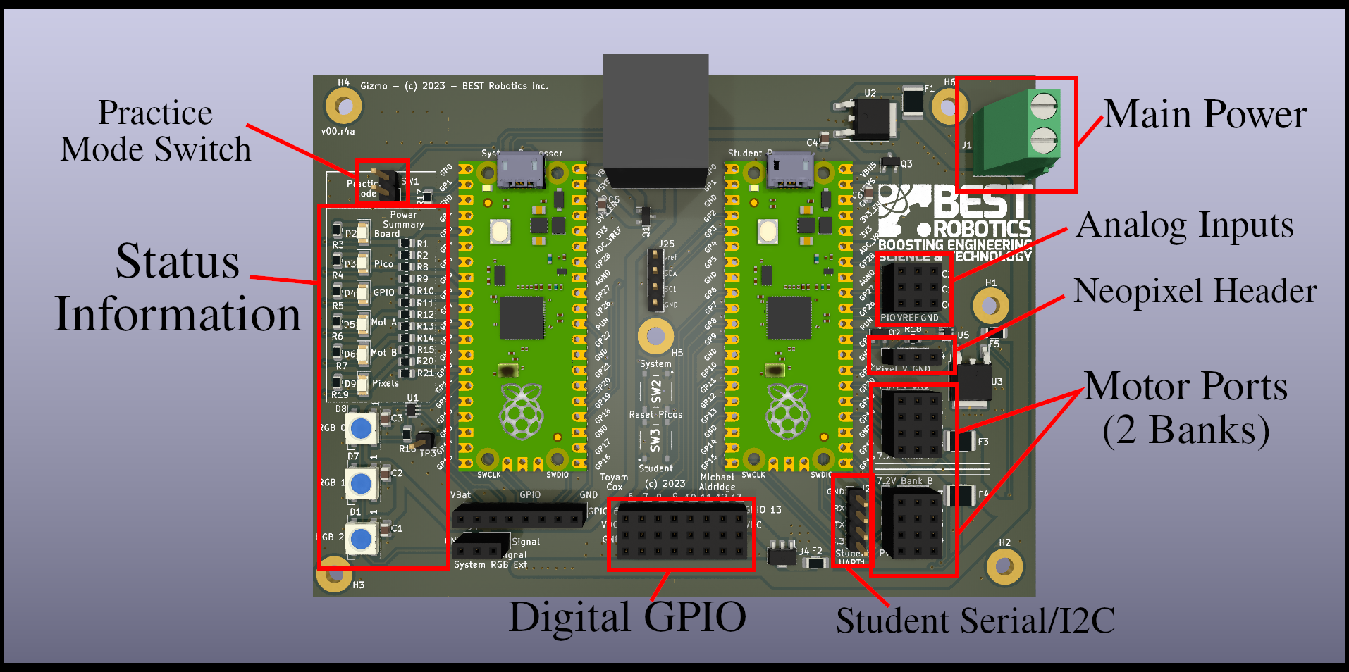
In the center of the board you can see the two Raspberry Pi Pico modules while run the system code and user code (your code). These devices are "socketed" meaning that they are not permanently attached to the board. This enables you to replace them if they become damaged, and to swap them out in order to isolate problems.
note
Note that the picture above is for hardware revision v00.r4b. You may have a different hardware revision with components in different places. If that's the case, pick your version from the table of contents to get more specific information.
The different components are called out on the board. Lets go through each section that's identified:
Main Power Connector
This screw terminal block provides the main power connection to the board. The positive terminal is the one towards the bottom of the board. When installing wires, make sure that you don't have any exposed metal sticking out of the connector, and tighten the screws until they are finger tight. You should be able to tug gently on the wires and not pull them free.
Analog Inputs
The Gizmo is equipped with 3 analog inputs. Analog inputs are able to read a range of values which fall into a defined range. The Analog inputs on the Gizmo are read with 12-bit precision, which means there are over 4000 discrete steps in its range. You can use an analog input in combination with a potentiometer to provide a very precise reference of the position of a component. If you use this precise feedback to drive a motor, you can create a custom high-power servo to drive components of your machine to specific places and maintain that position.
NeoPixel Header
NeoPixels are programmable, chain-able LED components that you can use to display information on your robot, make status information visible remotely, or just look cool.
info
Be aware that NeoPixel is a trade name for programmable integrated light sources popularized by AdaFruit. The drivers on the Gizmo are designed to support WorldSemi WS2812 Integrated Light Sources.
warning
In theory you can continue chaining NeoPixels end to end indefinitely, but putting too many together can draw too much power. The Gizmo is protected by self-resetting circuit breakers, but its still not good to add too many LEDs. As a rule of thumb, we design the header to support about 35 LEDs being powered on at any given time. You can have more than this connected, but don't turn them all on at once!
Motor Ports
Motor ports are able to supply high current power directly from the main power connector to larger peripherals, usually motors or servos. These ports provide power, access to a General Purpose Input/Output (GPIO) line and a ground connection. The ports are split into two groups to help you visually identify ports 1-4 and 5-8. Each group of 4 ports has an independent power supply limited to 4 Amps of continuous current draw.
Student Serial / I2C
For more advanced peripherals, this port provides access to a power connection and two GPIO lines. These lines are connected to special hardware on the Raspberry Pi Pico to enable either high-speed serial data or I2C bus communications. You can only use one communications protocol at once through this port.
Digital GPIO
The Digital GPIO ports provide access to 8 I/O lines that can be used for connecting to limit switches, IR sensors, or other input devices that allow you to sense the environment. Each I/O line has a 3.3v reference voltage and ground supplied. These lines are connected to the I/O lines on the Pico directly, so its important that you don't feed power into them from any other ports as this could damage the Pico.
Status Information
On the far left-hand side of the board is a vertical row of status lights. There are 6 lights which are specific colors and 3 lights which change colors. The fixed-color lights show you the status of the power systems on the board. If a light has gone out, that means that a corresponding system has lost power because the protection circuit tripped. Remove the main power supply by either turning off your power switch or removing the battery and inspect your wiring for short circuits (places where two wires touch directly without insulation) or components that are stalled out such as a motor that can't turn because something has jammed.
The 3 color changing lights provide information about key components of the Gizmo system. In order top to bottom:
-
The top-most light provides information about the wireless communications link. If the light is red it means that the Gizmo cannot find your driver's console. A yellow light means that the connection has been established, but the Gizmo hasn't yet started receiving information from the gamepad and field management system, and a green light lets you know you're good to go.
-
The middle light provides indication of what field and color you have been assigned. The light will blink the number and display the color. For example, if you were assigned to the red position of field 1, the middle LED would blink a single red pulse once per second. If you were on the blue position of field 3, you'd see 3 fast pulses of blue light once per second.
-
The bottom light provides an indication of battery voltage using a traffic light coloring system. If the light is green you have a freshly charged battery at max voltage. As the light changes color closer to red you should consider changing your battery. Its normal during use for this light to change colors as various components use power. The status of the light when nothing else is using power is the important indicator.
Prerequisites
Before you can start writing your own programs, its necessary to get your environment setup with some tools that support the Gizmo itself. You can find detailed guides for various programming languages and their respective tools in the table of contents. This section will focus on the initial setup to get the Gizmo ready to run.
Install the Gizmo CLI Tool
The gizmo CLI tool is a Command Line Interface (cli) tool. This means that it does not make use of the mouse, instead taking input entirely in text form and providing feedback entirely as text. The gizmo tool can help setup specific programming languages, but it also can help you get firmware installed, drive your robot, or even run a complete competition field system.
The gizmo tool is available on this page. From that page, find the most recent release that says "Latest" on it. You may need to scroll down.
Once you have located the latest release, download the appropriate files for your operating system. For most users, this will be 'gizmo_Windows_arm64.zip'. Download this file expand the zip archive. You can run the gizmo.exe file from anywhere, so save it somewhere you'll remember.
tip
If you're in IT and would like to deploy the Gizmo tools from a central location, reach out to the team and we can provide you with MSI packages suitable for silent installation via Group Policy.
Once you have the gizmo tool downloaded, you can open a PowerShell window and navigate to the directory where you saved the gizmo.exe file.
caution
If you find that the gizmo.exe file is missing. You may need to
add an exception to the Windows Real Time Protection system for the
folder you want to save the Gizmo tools into. Windows Real Time
Protection incorrectly fingerprints our tools based on the embedded
example code they contain as malicious. To add an exception to the
folder, follow this
guide
from Microsoft.
Always consult your IT or Information Security team prior to disabling or modifying your computer's security policy.
With PowerShell open, you can now type .\gizmo.exe and receive the following help output:
The Gizmo Platform provides servers for field control, configuration for your joysticks, and tools to program the system processor on your robot control board.

Usage:
  gizmo [command]

Available Commands:
  arduino     Configure Arduino tools for use with Gizmo
  completion  Generate the autocompletion script for the specified shell
  field       field cmdlets operate or configure a field
  firmware    firmware cmdlets manage the GSS firmware image
  help        Help about any command

Flags:
  -h, --help   help for gizmo

Use "gizmo [command] --help" for more information about a command.
Congratulations, you now have the Gizmo tools installed and are ready to proceed to the next steps!
Configuration
warning
The information on this page is largely historical. The GSS file has been auto-generated for several driver's station releases now, and running without the use of the driver's station is not a supported workflow.
Certain parts of the Gizmo system depend on information that cannot be inferred. To provide this information to the system, you must generate a configuration file that contains the relevant settings. The gizmo tool provides a guided walkthrough to generate these settings.
The file that this process results in will be named gsscfg.json which you may see referred to throughout this documentation as the Gizmo System Software configuration file. This file is used to specify certain critical parameters on both the System Processor and the Driver Station.
Generating the Config File
In a terminal window, execute the following command:
$ .\gizmo.exe configure
You will be asked a series of questions. Each question is described in detail below. Note that depending on your answers to some questions, later questions may be skipped when they are not required.
? Team Number
What team number should be associated with this Gizmo? The Gizmo uses the team number in various places to pair it with a driver's console, to identify itself to a field, and to seperate metrics out when multiple Gizmo devices are operating in concert such as a scrimmage or a competition. Your number should be an integer value below 9999.
? Network SSID and ? Network PSK
These questions will only be shown if you selected to use an external network controller. Enter your SSID and PSK in these fields. To generate these values, we recommend using the password generator from this site. Use one value as the SSID and one value as the WPA2-PSK. Remember to configure your network as a non-broadcasting network, and do not join any devices beyond the Gizmo and the computer hosting the gizmo tool which will be used to drive.
Driver Station
While it possible to use the Gizmo software and hardware with any computer, the Gizmo Team has developed software to provide an appliance-like experience using an embedded Linux system called a driver's station.
The station code is regularly tested using a Raspberry Pi Zero 2 W with a Waveshare Ethernet and USB hub. Though we don't actively qualify against the hardware, you should also be able to use our driver station system images on a Raspberry Pi 4B.
Physical Assembly
The driver's station comprises the Raspberry Pi Zero 2 W and the Waveshare board, which you will need to assemble. This need only be done once and once assembled there is no need to disassemble.
Consult the following graphic from the Waveshare documentation for assembly instructions, paying special attention to the order of the brass spacers that are used to assemble the PCB stack:
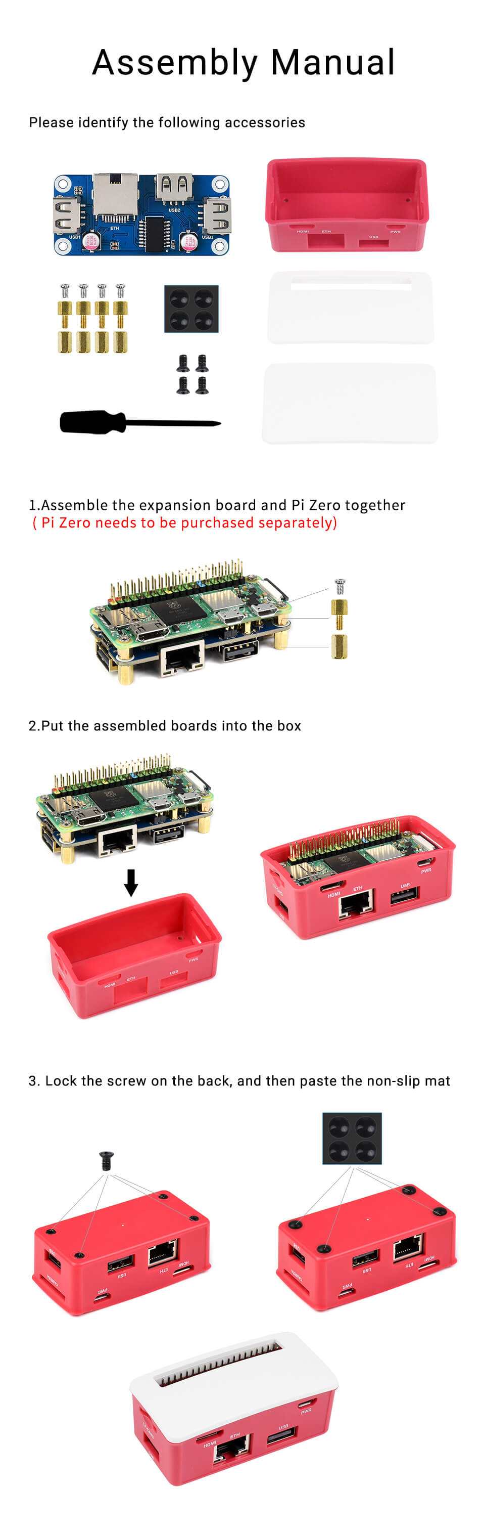
When installing the white cover plate, use the one without the cutout in it. Both are provided, but only the one without the cutout is required.
Software Installation
Once physical assembly is complete, you must install the software image that runs the driver's station. Ensure you have a means of writing a micro SD card for this step, using adapters if necessary.
tip
For first time setup of a never-before-used micro SD card, you can
instead flash ds-ramdisk.img.zip using Balena Etcher as described
in the appendix which will automatically
partition, format, and install the driver's station software to your
micro SD card. All other updates can then be performed using the
zip file as described below. Note that using Balena Etcher does
require one-time administrative access, and may not be suitable for
unprivileged student computers in schools.
Once you have imaged the disk with etcher, be sure to change the
name to GIZMO<NUMBER> as described below.
note
If this procedure doesn't appear to work for you, you may need to repartition your micro SD card. This can happen on some newer Windows 10 and Windows 11 machines where inappropriate defaults are selected.
If you have come here from the repartitioning guide, skip directly
to the step below where you extract the ds-ramdisk.zip file.
Obtain the latest system image from the GitHub releases page. For the driver's station, use the ds-ramdisk.zip file. The following instructions will be shown using Microsoft Windows, but similar instructions may be followed on other operating systems.
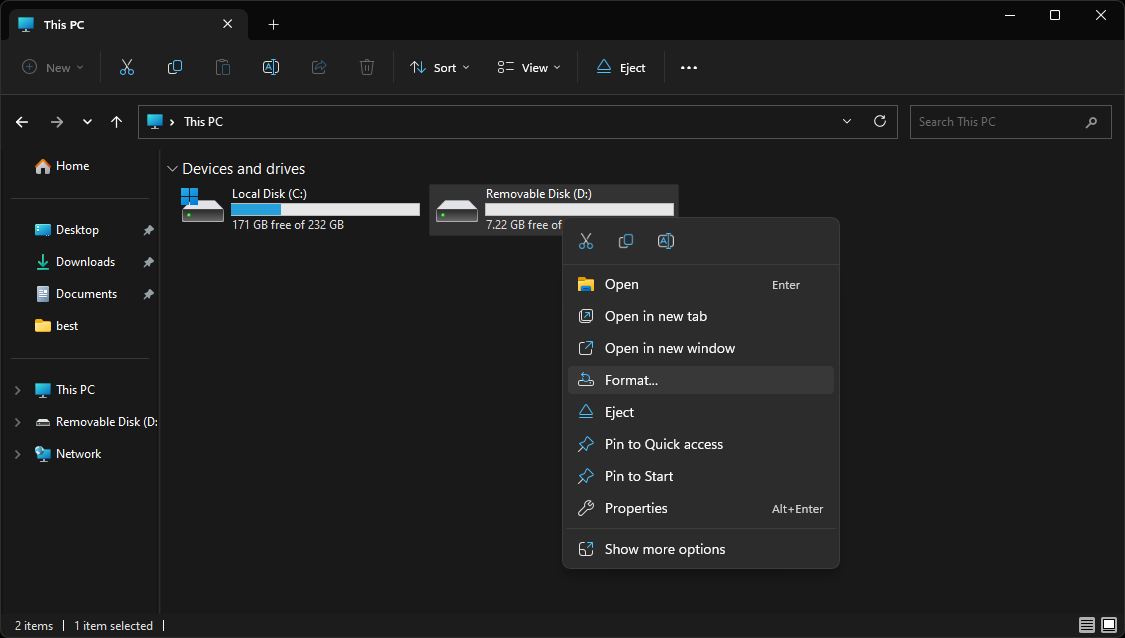
Begin by inserting the Micro SD card into a reader and plug it into your PC. Open Windows Explorer, select 'This Computer' and right click on the inserted (blank) drive. In the context menu, choose the "format" option.
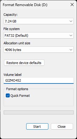
In the resulting format window, leave all options at the default, but fill in the Volume Label field. This field is case sensitive and should take the format of GIZMO<NUMBER> where <NUMBER> is the number of the team that should be associated with this driver's station. Do not left-pad the number field (#452 should be 3 digits, not having a leading zero).
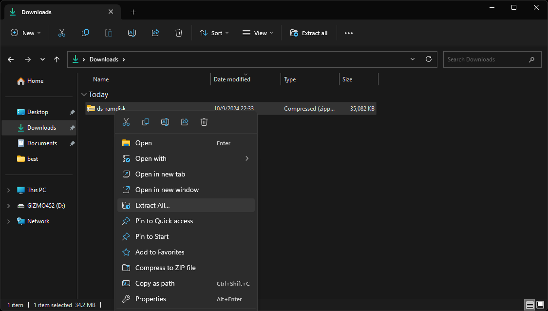
The format process will take several seconds, and once it completes the disk will re-attach as a named volume starting with GIZMO. Proceed by locating the ds-ramdisk.zip file you downloaded earlier and right-click it. In the context menu, select 'Extract All'.
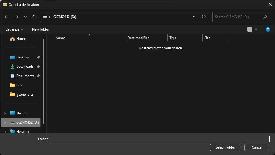
In the resulting file extraction wizard window, select "Browse..." which will open a file browser window. In this window, select the GIZMO disk from the left sidebar. Select the drive itself.
Once you have made your selection, the extraction wizard will be ready to proceed. Configured, it should look like this:
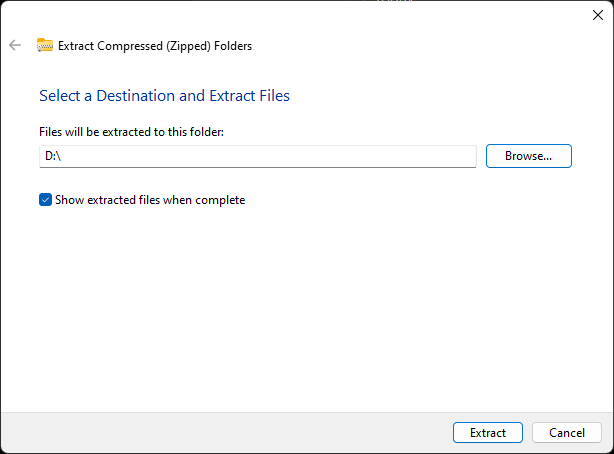
The extraction wizard will show a top level disk, in this case, the 'D' drive. Click 'Next' and a progress window will appear:
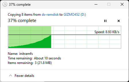
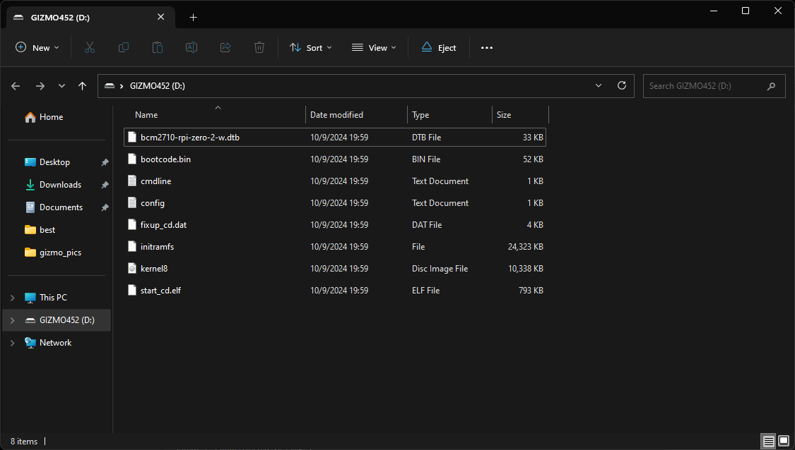
Once the extraction completes, the Gizmo disk will re-open and now contain files:
Eject the disk. Wait for either Windows to remove the drive and say it is safe to disconnect, or 30 seconds after clicking eject. Install the card into the labeled slot on the case labeled "TF Card". The card should be installed with the metal contacts facing the bottom of the case, and take care to insert the card into the reader. Its easy to miss the reader and just push the card into the case if you're not careful.
note
If you've been using the Gizmo for a while, you may be wondering
where the gsscfg.json file is. This file has been obsoleted. You
can still use one if you'd like, but the team number is now read
from the volume label, and other values are derived from the driver
station's hardware IDs.
Firmware Installation
Before you can use the Gizmo system with a gamepad and drive a robot around, it is necessary to install firmware, referred to as the Gizmo System Software (GSS).
While there is a lot of information on this page, the entire process should take you about 15 minutes given reasonable internet speed and a modern computer.
What is Firmware?
Firmware is a form of software. Historically, firmware would have to be installed at a factory or during final assembly of a system. This often involved high voltage programmers, powerful ultraviolet lights, or even advanced photolithography techniques to indelibly etch the program into the a physical structure on a devices memory chips. As you can imagine, having to have the firmware "burned in" made it a high stakes operation since there was no possibility to update or fix bugs after devices left the manufacturer's facilities.
As time has gone on, the term firmware has changed to mean any software that is installed at the most basic layers of a device that provides its core functionality. Firmware in this sense is no different than any other program, merely becoming yet another software program installed onto a device.
The Gizmo is no different, and the System Processor requires firmware to operate. This firmware is developed by the Gizmo Team and is written in C++ using the Arduino framework. You can inspect this code here. The firmware that runs on the System Processor is responsible for interacting with the wireless data link as well as providing control signals to the color changing indicators, driving the safety watchdog, and supplying information about gamepad and field state to the User Processor.
Installing the Firmware
Installation is easy. Connect the small end of a USB B-Micro cable to the System Processor. The System Processor located to the top left edge of the Gizmo when viewed with the indicator lights on the left and the connector blocks on the right.
Locate and hold down the bootsel button. If you are using a Gizmo without a case, you can use this graphic from the Raspberry Pi Foundation:

If you are using a Gizmo inside a case, the button will be located in the same place, but guarded by the case. Depending on which version of the various case designs you have selected to use, you may need an unfolded paperclip to reach the button.
Using the Driver's Station
Once you have located the button, press and hold it while plugging the USB cable into the driver's station. The driver's station will detect the Gizmo in firmware-mode and copy the system firmware to it, then reboot it. This process takes about 2 minutes. For first time binding (fresh out of box system processor) the Gizmo will then automatically bind to your Driver's Station.
note
This only works for 1.x Gizmos. All commercially available Gizmos are in the 1.x series, so this will only fail if you happen to have a pre-release board.
Using a Laptop/Desktop
Once you have located the button, press and hold it while plugging the other end of the USB cable into your computer. Your computer will detect the Gizmo in mass-storage (thumb drive) mode, and it will be attached as a removable drive.
Obtain the latest firmware release from here. Your board has a specific version number, printed at the top right of the case. For most users, this is v1.00. You need the uf2 file referencing that version number, and can find it in the "Assets" section located at the bottom of the card.
Simply drag-and-drop the uf2 file from above onto the drive. After a few seconds, the drive will disconnect and the light on the System Processor will begin to glow then flash.
Bind the Gizmo to a Driver's Station
When you install firmware for the very first time, the Gizmo won't know what driver's station its supposed to talk to. The process of connecting a Gizmo to a driver's station is referred to as binding, and is a fully automated process.
With the driver's station powered on, connect the system processor to any free USB port on the driver's station, and power on the Gizmo. If the Gizmo has never been bound before, the network and position status lights will rapidly blink. If the Gizmo has been paired before, you can re-enter pairing mode by pressing the bootsel button for 2 seconds after all the lights on the board have turned on. The configuration will be synchronized between the driver's station and the Gizmo, and the Gizmo will reboot.
note
If you leave your finger on the bootsel button too long it will still be held down when the Gizmo reboots. If this happens, the pattern of lights will stop changing in the status indicators. Just unplug the USB cable and turn the Gizmo off and back on again to complete the reboot process.
After a few seconds, the Gizmo will connect to the Driver's Station and begin communicating.
Field Services
The gizmo tool provides certain services related to a robotics competition field. These services include field location as well as control signal transmission. Metrics, logging, and statistical information is also provided by the FMS.
The FMS contains several components, depicted in the following diagram:
At the center of the network is the Scoring Table box, which connects to the FMS Workstation, any Field Boxes, and Internet if available. The FMS Workstation is a Linux PC running the administrative software that powers the FMS, and the Field Boxes provide a means of access to these services via wired interfaces for Driver's Stations and Wireless interfaces for Gizmo devices.
Workstation Setup
The Field Management System (FMS) consists of hardware, software, and network components. The software runs on a dedicated workstation referred to as the FMS Workstation. The Gizmo team recommends a Raspberry Pi 400 computer to function as the FMS Workstation. Though an untested configuration, the Raspberry Pi 4 should also work if you prefer to supply your own keyboard and mouse instead of using the integrated keyboard and bundled mouse from the Raspberry Pi 400.
Since the quality of the micro SD card has a direct relationship to the performance of the FMS workstation, you are strongly encouraged to invest in a name-brand high performance micro SD card. The Gizmo Team regularly tests using Sandisk Extreme cards ranging from 32GB to 64GB. Regular handling of these cards can lead to damage, so having a space is a good idea, and take regular backups of any critical data.
Install the System Image
The FMS Workstation System Image is a complete, ready to use system software image for the Raspberry Pi. Obtain the latest system image from the GitHub releases page. For the FMS Workstation, use the fms.zip file. After unzipping the file, you'll have a file called fms.img.
To write the image to the SD card, you have a few choices. If you're on a mac or a Linux machine, you can use dd. On Windows you can use Win32DiskImager. If you've never written disk images before, the Gizmo team recommends you use Balena Etcher which is available for all platforms, and guides you through the process.
tip
Balena Etcher Portable edition can be used without needing to install. This can be convenient to not clutter your machine with extraneous programs, or to write files from a machine where you do not have administrative permissions to install new programs.
For a complete walkthrough of what Balena Etcher looks like, review the image writing process from the appendix (this page).
First Boot
The first time you boot up your FMS Worstation it will perform a number of initial setup tasks. This process may take some time while the filesystem is expanded to use all available space on your micro SD card, services are started, and initial configuration data is written out to the system.
After the initial setup is complete, you will be greeted with a desktop that looks like this:

warning
The user you are logged in is called "admin". Do not create any additional users or change parameters for this user in any way unless explicitly advised to do so by the Gizmo team. A large amount of automated configuration data for the FMS expects this user to exist and you to be logged in as it, and these assertions are enforced.
checkpoint!
You have now completed workstation setup. Proceed through one of the available setup workflows to continue.
You are now ready to proceed with setup. We recommend and support using the Graphical Setup Experience, but you are free to disregard this advice if you have a compelling reason to use one of the unsupported setup workflows.
Graphical Workflow
The Graphical Workflow is the recommended method for all users installing and operating the Gizmo FMS. This workflow is primarily web-based with a few text interfaces that are used for early system configuration.
Prior to completeing tasks in this section, you should complete the Workstation Setup tasks which involve installing the software image on the FMS.
Initial Tasks
Once the FMS system image is installed and you are greeted by the desktop, there are a few tasks to complete prior to actually setting up the FMS itself. Briefly, you'll need to accomplish the following:
- Connect the FMS Workstation to a Wi-Fi network.
- Set the timezone and clock.
- Download certain restricted artifacts that cannot be distributed with the system image.
- Change the default password. (Optional, but highly recommended)
When the FMS is booted you will always be greeted by the System Configuration screen. This screen is blue and looks like this:

This screen can be navigated by using the arrow keys and return to make a selection. Start by changing the default password for the admin user. The password that is set by default is gizmo.
Next, select the option to connect to Wi-Fi, which will launch a new window to select your network. The Wi-Fi selection window looks like this:

Select your network, click Connect, and input a password if prompted. After a few moments, the strength indicator will change to show you are connected, and you may dismiss the Wi-Fi screen by clicking on the close button at the top right of the window.
You are now ready to launch the FMS Web Admin system, which will be used to complete the rest of setup. Do so now by selecting 'Launch Gizmo Platform' from the menu, and wait for the firefox window to appear. The Gizmo landing page looks like this:

Select the option for Administration, and enter the username admin and the password you selected above. You'll be greeted by the administrative landing page which looks like this:

Select "Out of Box" from the setup menu, which will return a page that looks like this:

Click "Set Timezone" then wait several seconds for the action to complete. Next click on "Fetch Tools" and wait for the download to complete. Finally, click on "Fetch Packages" and wait for the series of downloads to complete. If you encounter an error, these actions are safe to retry until the system succeeds.
Roster Setup
The FMS is able to provide network services to Gizmos by knowing what teams are on what field locations at any given time. To do this, a roster must be provided. The FMS will import the roster from a CSV with the following headers:
Number,Name
The column names are case sensitive and must appears as the first two columns in the file. Arbitrary columns may appare after the first two and will not be read.
Select 'Roster' from the setup menu and this page will be displayed:

After you select a file, the file will be parsed and displayed as it will be imported. The parsed content will look like this:

If you are satisfied with the teams that have been parsed, click 'Submit Roster' and the system will update its configuration. You can change the roster later, and team numbers that appear in both the old and new rosters will not be affected.
Prepare Hardware
In the graphical workflow we prepare the hardware before configuring fields, as the process of preparing the hardware will retrieve certain identifiers that are used in configuration later.
Select 'Flash Device' from the setup menu, which will provide more detailed information on the resulting page:

Once you select the device you will be flashing and press 'Begin Flashing' text will appear in the gray box below the menu. Connect an Ethernet cable between the FMS Workstation and the 1st Ethernet port on the powered off device. Then connect the power to the device while pushing and holding the device's reset button. Release the button when the text 'Booting device' appears in the logs window.
A successful installation will look like this:

Make note of the MAC address printed in the last line when flashing your field boxes as you'll need this in the next step to setup your fields. Complete flashing of all devices before proceeding from this step.
Configure Fields
The FMS needs to be told what hardware goes with what field. Most events will only have a single field, but for larger events multiple fields allow multiple parallel matches to be played. When using multiple fields, take care to label the hardware with its identity so no mishaps occur with placing the wrong radio at the wrong field.
Begin by selecting 'Fields' from the setup menu, which will display the main field listing:

Click on 'Add Field' to add your first field, and input the hardware ID you saved during hardware setup:

You may specify the channel now, or change it later. When you are satisfied, click save and the field will be saved into the configuration.

Continue to add as many fields as you will have at your event, ensuring that you make note of what field ID you assign to each physical device.
warning
It is not supported to remove fields after the network has been bootstrapped. Doing so will result in an FMS crash that is difficult to recover from, and likely will require assistance from the Gizmo developers.
After configuring fields, review any additional configuration as required before proceeding to the network bootstrap.
Additional Settings
The only required settings that must be configured to use the FMS are the team roster and field hardware IDs. All other settings will default to sane defaults, however you may wish to adjust these settings based on your specific event.
External Integrations
The FMS can be automatically driven by external integrations. These integrations may be configured from the 'Integrations' option in the setup menu. The page looks like this:

Check or uncheck the boxes next to integrations to enable or disable them. Ensure you save the configuration before navigating away from this page.
WiFi Network
The FMS hardware provides a so-called "Infrastructure Network" that you can use as a general purpose wireless network to connect additional computers, projectors, or other game infrastructure to. This network is considered a trusted network, so teams should not have access to it. You may view or change the generated SSID and PSK by selecting 'WiFi Settings' from the setup menu.

Network Bootstrapping
The FMS makes use of a sophisticated programmable network architecture which requires one-time bootstrapping per competition. This bootstrap procedure should take about 10 minutes. You'll need the FMS Workstation, the Scoring Box, and any Field Boxes.
Start with the network devices powered off and unplugged. Connect an Ethernet cable between the FMS Workstation and port 2 on the Scoring Box.
Select 'Net Bootstrap' from the setup menu, and you will be greeted by this interface:

Click on 'Initialize' followed by 'Phase 0'. Follow the prompts displayed in the gray box and when told to do so, power on the scoring box. Follow the prompts to complete network device flashing. Once complete, the gray box will look similar to this:

After finishing the bootstrap, reboot the FMS workstation by holding the power button for 4 seconds until the device turns off, then press the button again to boot the workstation again.
Connecting Gizmos
Before a device powered by a Gizmo can be used on a field, it must be bound to the FMS. This process is extremely similar to the process of binding a Gizmo to the Driver's Station in that it uses a USB cable to the System Processor and a 2 second press on the System Processor's BOOTSEL button to initiate binding. The primary difference is that when binding to the FMS you will be prompted to identify which team the Gizmo being bound belongs to.
Loading the Bind Screen
From the admin interface of the Gizmo FMS, select Operate > Bind Gizmos. This will open a page which does not have the menu bar. If opened in firefox, you will see the following screen:
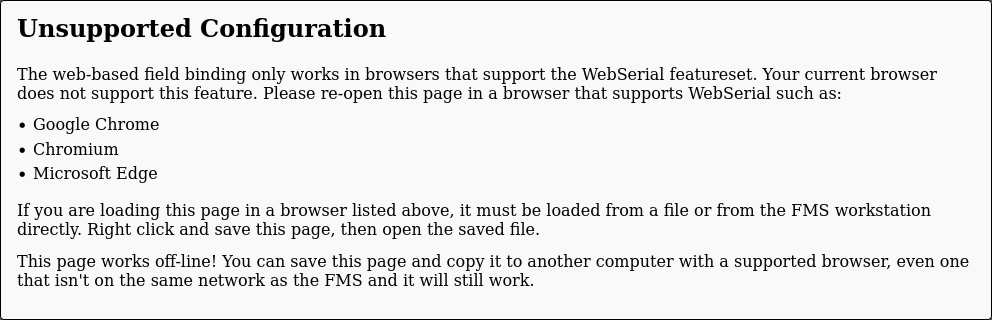
The web-based Gizmo Binding workflow makes use of features that are only available in Google Chrome and Chromium-based browsers, namely WebSerial. The web-based binding workflow is meant to run on a machine that will be accessible to teams, not necessarily the FMS Workstation. For this reason, you can right-click and save the page as a standalone HTML docuemnt which can then be copied using cloud storage, email, or other network methods to the target machine.
warning
Do not distribute this file to un-trusted entities, especially teams. It contains the encryption keys for your FMS and must not be distributed to untrusted parties.
Setting Up
There is a one-time setup task required to be able to use the web-bind page.
Once you have copied the file to a computer that will be used for binding and opened it in a Chromium-based browser, you'll have a screen that looks like this:

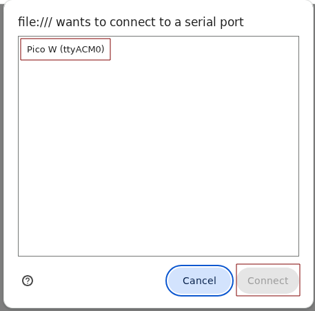
Scroll down and click on "Request Port" at the bottom center of the screen. A dialog will open asking you to select a device to grant access to. Plug in any Raspberry Pi Pico W (doesn't need to even be in a Gizmo) and select the Pico from the list:
It is only necessary to perform this procedure once. After permission has been granted, future Gizmos can be plugged in and the page will handle fully automatic config binding without manual intervention.
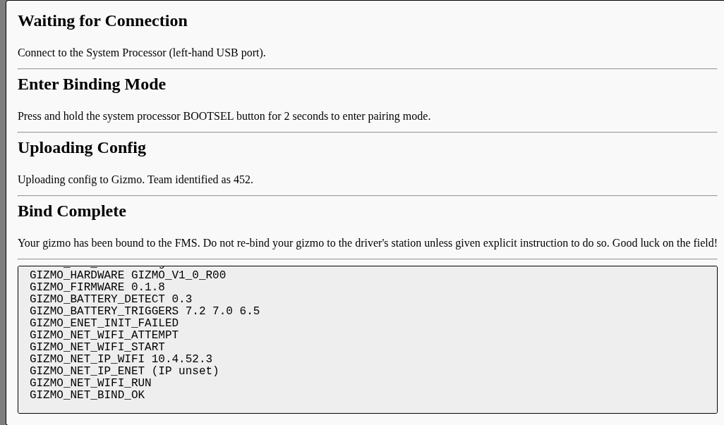
Binding a Gizmo
Once setup is complete, you can connect to the system processor with a USB cable and the page will recognize that you have connected a Gizmo for binding:
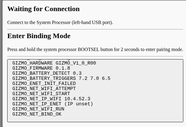
Binding will complete automatically after the BOOTSEL button is held for 2 seconds, and the page will reset itself after the USB cable is disconnected, or a timeout of 2 seconds. The successful binding looks like this:
Operating the FMS
The FMS can be operated in of two ways:
-
Fully Manual - Team mapping is managed by a human operator who keys in each match when its time to change the field setup.
-
Remote Managed - The FMS is called by a remote system which maintains the schedule and inserts matches as required.
Manual Operation
To manually setup a match, select 'Stage Mapping' from the 'Operate' menu. The mapping interface looks like this:

Setting up a match is as easy as selecting the teams from the drop downs for each field position, and then selecting to save the stage mapping. You can edit a stage mapping at any time without disrupting an active match. This is what the interface looks like with a mapping staged:

When you are ready to make the stage mapping active, click on 'Commit Staging Map' and all configured fields will cycle to the currently staged set of teams. This will take about 10 seconds, resulting in the following view:

The right-most column of the table shows which teams are physically present and connected to the field, with the location being shown as the location of the Driver's Station. This information is extremely handy when coupled with the 'Map Teams Present' button. This button immediately updates the active mapping to match the real locations of whatever teams are at the field at the moment it is clicked. This will disrupt any active communication, so do not click on it during a match. The active mapping feature is designed as a speed enhancement for running practice or ad-hoc matches where there is not a set order that teams will appear at a given field position.
Console Setup Workflow
warning
This is an advanced workflow that is not necessary for the vast, vast majority of users of the Gizmo platform. The console setup workflow was the original setup workflow to build the FMS setup prior to the introduction of the web interface, and is no longer recommended. If you are trying to build an FMS setup on an unsupported hardware configuration, such as an amd64 computer, you should follow the instructions in Hard Mode instead.
The Console Setup workflow performs most setup tasks using textual commands entered into a terminal window. You can use any terminal you like, even completing these steps remotely logged in via ssh. The Gizmo FMS workstation ships with a handful of terminal emulators installed, which can be found in the applications menu.
Prior to completeing tasks in this section, you should complete the Workstation Setup tasks which involve installing the software image on the FMS.
Initial Tasks
Upon logging in you must connect the FMS workstation to wifi in order to download some utilities and files that are not distributable.
Connect to wifi by right clicking anywhere on the blank space of the desktop, or use the menu in the lower left hand corner, and select "iwgtk" from the network menu:
Settings > HardwareSettings > iwgtk
Select your wifi network and click connect, entering the password if your network requires one.
Right click anywhere on the blank space of the desktop, or use the menu in the lower left hand corner, and select the XFCE4 terminal from:
System > TerminalEmulator > Xfce Terminal
note
You are also strongly encouraged to change the FMS password with the following command:
$ passwd
This will prompt you for your current, new, and confirmation of new
passowrds. The default password is gizmo.
With the terminal open, execute the following commands:
$ sudo tzupdate
This will set the timezone based on your location. It may print errors depending on how far off the clock actually is.
Now you must retrieve some restricted packages that are used under license from Mikrotik. The following commands will retrieve these files from the internet.
$ sudo -u _gizmo gizmo fms setup fetch-tools
$ sudo -u _gizmo gizmo fms setup fetch-packages
note
Note that the sudo command is changing the active user to
_gizmo. All components of the Gizmo FMS run as this special user,
and store state in /var/lib/gizmo. Be careful to only ever
interact with this directory as this user.
Updating the Gizmo Binary
note
You only need to update when a new version is released. If you just installed, you're already on the latest version.
From time to time the Gizmo application receives updates. To update the software on the Gizmo FMS workstation, execute the following commands in a terminal:
$ sudo xbps-install -Su
$ sudo reboot
The update command will tell you how much space is required and how much data will need to be downloaded from the internet.
Configuration
Before the FMS can be initialized, the system must be configured. This step must be completed after the FMS system software has been installed, since it must be completed from the FMS Workstation.
Prior to completing this step, obtain a CSV containing your team's information. The information should be in the following format:
Number,Name,Hub,Table
The headers should be as shown above. The FMS will parse this file to construct a record for each team. To perform initial configuration, run the configuration wizard by invoking:
$ sudo -u _gizmo gizmo fms setup wizard
You will be asked a series of questions.
? Overwrite existing config?
The FMS ships with a blank "dummy" configuration file which is required to allow the web interface to start. Configuring using the console will overwrite this file, and you must confirm this overwrite to proceed.
? Specify teams CSV file
This question prompts for the CSV containing your team information as listed above. Either type the path to this file or press tab to show files in the current directory.
? Loaded 21 teams, does this look right?
The wizard will parse the file you provided and tell you how many teams were in it. If the number looks okay, answer yes, otherwise answer no to exit the wizard. If you need to exit the wizard, check that the file is not malformed.
? Select the number of fields present
Select between 1, 2, or 3 fields. If you need to run more than 3 fields concurrently, contact the Gizmo team to receive further instructions on how to configure this larger number of fields and recommended hardware for hosting very large events.
? Input the MAC address for ether1 for field 1 (label on the bottom)
note
This question will be repeated for each field that you've told the system you have.
Locate the Field Box that you will use for each field prompted. On the bottom of the device there is a label containing various information. Locate the line beginning with E01: which will be followed by a MAC address. Input the sequence of 12 hexadecimal characters exactly as printed, including the colons. This field is case-insensitive.
? Select the channel to pin this field to. You can change this later.
note
This question will be repeated for each field that you've told the system you have.
Select what wireless channel this particular field will be bound to. Your choices are 1, 6, 11, or Auto. Auto will automatically scan for and select a lightly used channel. If you have other wireless systems that you cannot disable, it is wise to avoid the channels in use by those systems.
You can change this later by running gizmo fms setup change-channels which will re-prompt for each field the channel you want it on. After making your selection, run gizmo fms net reconcile.
? Read-only user password (username: gizmo-ro)
In the unlikely event you need to log into the interface on the field network directly this username will be available to you on the Scoring Box and all Field Boxes. The generated password is a good mix of security and ease of use, so unless you have a need to change it, accept the default.
? Make infrastructure network visible
The infrastructure network is the network that operates on the 5Ghz radio and is available for you to connect tablets, projectors, and other assorted devices to. It operates independent of any robot channels. In general making the network will improve ease of use, and making it invisible does not improve security meaningfully.
The primary advantage of making the network invisible is to discourage people from asking for access to it, and to prevent clutter from showing up in WiFi menus.
? Infrastructure network SSID gizmo
This is the SSID of the infrastructure network described above. You can freely change this to any value you wish as it is not used internally by any of the FMS components.
? Infrastructure network PSK
A password will be automatically generated for the infrastructure network, though you can change it to any value you desire. Note that the password will not be obscured in this interface.
? MAC Address of the FMS
The FMS has a pinned address pre-allocated for it by the Scoring Box DHCP server. In order to pin this address, the MAC address must be known. This option will be pre-populated with the correct value when running the wizard from the FMS Workstation. Do not change this value unless you are using another machine to perform this configuration and will subsequently transfer files to the Workstation (very advanced use case).
? Select Integrations
The FMS can integrate with other 3rd party software. Use the arrow keys to navigate the checkboxes and space to mark or clear each box. Press enter to accept your selection. You can change this later. Integrations are discussed in detail in the Integrations Section.
? Configure really advanced network features?
Answer no to this question unless you have received specific instructions otherwise.
Hardware Preparation
Having completed the initial configuration wizard, you are now ready to install the network device operating software. This is an automated process which takes about 5 minutes per device you need to install. At minimum, you will need to install the software on one Scoring Box and at least one Field Box. If you have more than one field, you'll need to repeat this process for each Field Box.
Before you begin, make sure you have the following:
- The Scoring and Field boxes.
- A paperclip or other suitable instrument.
- A network cable to connect the FMS Workstation to the device being provisioned.
- The power supply for the Scoring Box - this PSU is interchangeable with all other boxes.
Conventionally, start by installing the software on the Scoring Box. Do this by connecting port 1 of the Scoring Box to the FMS workstation directly using an Ethernet cable. Do not connect power to the Scoring Box. Once you have done this, launch the flash-device utility. You will see the following message:
$ sudo -u _gizmo gizmo fms setup flash-device
Welcome to the Device Flash utility.

This process will guide you through the process of installing the most
recently confirmed working firmware on your field device.

Before you begin, you should ensure that you have the field device, an
unfolded paperclip or similar instrument, and a cable to connect port
1 of the field device (says 'Internet'), and the FMS workstation (this
computer).
? Select the type of device you are flashing Scoring Table Box
? After you confirm this message, hold down the reset button using the
paperclip and connect power.  You may remove the paperclip after you
see a message containing the phrase 'client'.

Ready to proceed (y/N)
Notice that the first prompt asks which type of box is being provisioned, and in the above example the Scoring Table Box option was selected.
After you press Y and confirm your selection, press and hold the reset button on the Scoring Box and then connect power. The USR light will blink approximately 12 times and then go out. Once the light goes out you may release the reset button and you should see the software installation process start. In the unlikely event that the software installation process fails for any reason, it is safe to restart.
The installation process will look similar to this:
2025-08-03T16:25:37.549-0500 [INFO]  flash-device: Writing configuration to file: path=/tmp/3206896280.rsc
2025-08-03T16:25:37.567-0500 [INFO]  flash-device: Version: 7.17(2025-01-16 09:26:27)
2025-08-03T16:25:37.570-0500 [INFO]  flash-device: Will reset to default config
2025-08-03T16:25:37.570-0500 [INFO]  flash-device: Will install devices only once
2025-08-03T16:25:37.584-0500 [INFO]  flash-device: Using interface eth0
2025-08-03T16:25:37.584-0500 [INFO]  flash-device: Using interface eth0
2025-08-03T16:25:37.584-0500 [INFO]  flash-device: Waiting for Link-UP on eth0
2025-08-03T16:26:18.591-0500 [INFO]  flash-device: Waiting for RouterBOARD...
2025-08-03T16:26:18.740-0500 [INFO]  flash-device: Assigned 192.168.88.1 to 78:9A:18:D3:24:C4
2025-08-03T16:26:20.385-0500 [INFO]  flash-device: Booting device 78:9A:18:D3:24:C4 into setup mode
2025-08-03T16:27:05.789-0500 [INFO]  flash-device: Formatting device 78:9A:18:D3:24:C4
2025-08-03T16:27:31.788-0500 [INFO]  flash-device: Sending packages to device 78:9A:18:D3:24:C4
2025-08-03T16:27:35.844-0500 [INFO]  flash-device: Packages and configuration script sent to device 78:9A:18:D3:24:C4
2025-08-03T16:27:35.899-0500 [INFO]  flash-device: Rebooting device 78:9A:18:D3:24:C4
2025-08-03T16:27:35.899-0500 [INFO]  flash-device: Successfully finished installing the device with MAC address 78:9A:
2025-08-03T16:27:35.900-0500 [INFO]  flash-device: Flashing complete, you may now disconnect cables.
To install the software on Field Boxes, repeat the process as described above, with the only change being the selection of the box type.
Bootstrap Network
After installing software on all of your Scoring and Field boxes, its time to connect them all together and perform network initialization. This process should take about 15 minutes.
You will need:
- Provisioned Scoring Box.
- One or more provisioned Field Boxes - 1 per field.
- Scoring Box power supply.
- Ethernet cable to go between FMS Workstation and Scoring Box.
- Ethernet cables to go between the Scoring Box and each field.
Start with the FMS Workstation connected to port 2 of the Scoring Box. You may connect your WAN connection to port 1 if you have it available, but it is not required at this time. Ensure that the FMS Workstation has a WiFi connection with internet available.
Connect power to the Scoring box and wait approximately 2 minutes for it to finish initialization. Do not connect any Field Boxes yet. Begin the bootstrap procedure with the following command:
$ sudo -u _gizmo gizmo fms net bootstrap
You will be presented with a message summarizing most of the above information:
You are about to complete out of box provisioning for your field.
Prior to this point, you should have used the flash-device command to
install the most recent qualified system image to your scoring box and
field box or boxes.  Begin the process with all devices powered off.

Connect the scoring table box's second port (the FMS port) directly to
the FMS workstation (this computer).  Connect no other cables or
devices.

Power on the scoring table box and wait approximately 2 minutes for
it to boot.  Once the device has booted (pattern of lights has
stabilized), confirm this dialog and the scoring table box will be
programmed.  You will receive more instructions on when to connect
field boxes after the main scoring box provisioning completes.
? Acknowledge and Proceed (y/N)
You will see a large amount of text scroll by that provides detailed information on which resources have been provisioned and which resoures are being actively configured. After some time, the provisioning workflow will pause and prompt you to connect the cables to your Field Boxes:
The scoring box has been successfully programmed for your event.
Connect your field boxes to ports 3-5 on the scoring box at this time.
If you are not using a PoE enabled scoring box, connect power to your
field boxes at this time.

Once connected, wait approximately 2 minutes for your field boxes to
finish booting (pattern of lights has stabilized) and then confirm
this dialog.  You will see some error messages printed as the initial
configuration is programmed, this is normal.

This process can take up to 10 minutes to complete.

? Acknowledge and Proceed (y/N)
If you have the PoE version of the Scoring Box, connecting only the network cables will be sufficient. Cables should be installed between port 1 of each Field box to ports 3-5 of the Scoring Box. Power will be supplied over the network cables and you should see the lights come on with each Field Box. If you are not using the PoE version of the Scoring Box, you will need to additionally connect the Field Box power cables.
After connecting cables, wait approximately 2 minutes for the devices to power and and complete initialization before proceeding. Once you proceed the process will continue automatically until the Field boxes are fully provisioned.
After all provisioning has completed, you will receive the following message:
$ 2024-05-08T16:44:54.077-0500 [INFO] bootstrap-net: Provisioning Complete
The final step is to run the following command which will resolve a handful of items that are set to different values during bootstrapping:
$ sudo -u _gizmo gizmo fms net reconcile
The command will run for approximately 2 minutes and validate your entire network configuration. If at any time you think your network configuration may have become corrupt, you can re-run the reconcile command to validate the entire configuration end-to-end.
Connecting Gizmos
Before a device powered by a Gizmo can be used on a field, it must be bound to the FMS. This process is extremely similar to the process of binding a Gizmo to the Driver's Station in that it uses a USB cable to the System Processor and a 2 second press on the System Processor's BOOTSEL button to initiate binding. The primary difference is that when binding to the FMS you will be prompted to identify which team the Gizmo being bound belongs to.
gizmo fms config-server
The gizmo tool provides a command for rapidly binding multiple Gizmos to the FMS. For this reason, it is recommended that you perform binding from the FMS workstation.
Launch the tool by running sudo -u _gizmo -g dialout gizmo fms config-server which will initialize and then wait for a Gizmo to request configuration. Connect a USB cable from the FMS workstation to the System Processor on the Gizmo to be bound, then press and hold the BOOTSEL button for 2 seconds.
You will see output similar to the following:
2024-05-08T22:10:56.258-0500 [INFO]  config-server: Found a port!: port=/dev/ttyACM1
? Select configuration to bind to this Gizmo  [Use arrows to move, type to filter]
> team470
  team451
  team459
  team461
  team465
  team460
  team463
A list of all teams that the FMS is aware of will be presented. You can either arrow through this list or type the first few characters of the team name you wish to select. Pressing enter will confirm your selection and upload the desired configuration to the connected Gizmo.
tip
You can call the config-server with --oneshot to have it exit
after each one. This may be more intuitive to some users and is
also easier to avoid accidentally double flashing a Gizmo.
Operating the FMS
The field can be operated in of two ways:
-
Fully Manual - Team mapping is managed by a human operator who keys in each match when its time to change the field setup.
-
Remote Managed - The FMS is called by a remote system which maintains the schedule and inserts matches as required.
In either case, you first needs to start the FMS.
Checking the FMS is Running
The FMS runs as a system process. You can check that it is running by executing the following command:
$ sudo sv status gizmo-fms
If the FMS is running, you should see the following output:
$ sudo sv status gizmo-fms
run: gizmo-fms: (pid 3709) 191s
The PID and number of seconds displayed will be different, the important item is the run state from the start of the line. If you believe the FMS is not operating correctly, you can restart it with the following command, which will have the output shown below:
$ sudo sv restart gizmo-fms
ok: run: gizmo-fms: (pid 3805) 1s
Manual Operation
To manually map a match, use the gizmo fms remap command to configure a match. The command will prompt sequentially for each quadrant of each field. If you wish to skip a field, enter a dash (-). If a team is currently on the field, that team will be offered to you as a default that you can press enter to accept.
Since this is an authenticated administrative operation on the FMS, you'll need to authenticate. Gizmo CLI tools expect to retrieve this information from the environment variables GIZMO_FMS_USER and GIZMO_FMS_PASS. Set these variables with the following commands:
$ export GIZMO_FMS_USER=<username here>
$ export GIZMO_FMS_PASS=<password here>
The remapping workflow will look similar to this:
$ gizmo fms remap
Enter new mapping
? field1:red 450
? field1:blue -
? field1:green -
? field1:yellow 472
This will place team #450 on the Red quadrant of field 1 and team #472 on the Yello quadrant of field 1.
At any time you can remap the teams that are active, but doing so will disrupt communications to other Gizmos on the same field. As long as an active match is not in progress and no automation is remapping it is safe to remap a match at any time, even if using automatic control.
Automatic Operation
Automatic operations are available via various integrations.
Hard Mode!
danger, will robinson!
Absolutely nothing in this section is supported. This is provided for your entertainment and information, and is supposed to help you understand what exactly is inside of the FMS image file that's provided for the Raspberry Pi.
You do not need to read, engage with, or even acknowledge this section to use the FMS or operate the Gizmo system.
Life not interesting enough? Nothing to do on a rainy afternoon? One last day of summer, one more day before school has begun? Lets have some serious fun and build the entire FMS, by hand, from nothing. And for added bonus points, we'll do it on a conventional amd64 system to really prove we know how it works and what it does.
In case it wasn't clear, this section of the manual deals with very advanced concepts that are just for fun, and let you know what the magic is inside the system. Broadly, we'll build the FMS using a few steps:
- Install and Configure Void Linux
- Install the FMS System Software
- Flash Network Devices
- Bootstrap the Network (by hand)
Lets begin.
Install and Configure Void Linux
The FMS expects to run on top of Void Linux. While the Gizmo tools are statically compiled Go, changing the underlying Linux distribution is beyond the scope of even this document. If you're really interested in changing event that, its possible and the Gizmo team wishes you Godspeed and good luck.
We'll use Void Linux for x86_64, and we'll use the musl flavor. The musl flavor substitutes the conventional glibc flavor for the much more compact musl library developed by Rich Felker. This library has the bare minimum in it to satisfy the requirements of the C library interface.
Installing Void is a generic process, and you are encouraged to consult the upstream documentation. The only constraint you need to keep in mind is that the Gizmo tools presently hard-code the user that you're expected to run as, so its important to make sure that your user account has a login name of admin.
Disable "predictable" Interface Names
Recent versions of most Linux distributions use a so-called "predictable" interface naming function. If you have a magic decoder ring and know the precise hardware layout, data-plane architecture, and chip interface types its possible to predict the interfaces. Since the computer used in this guide has one wireless interface and one wired interface its much easier to turn off this "predictability" and know that the wireless interface will be wlan0 and the wired interface will be eth0.
Do so by changing the value of GRUB_CMDLINE_LINUX_DEFAULT in /etc/default/grub:
GRUB_CMDLINE_LINUX_DEFAULT="loglevel=4 net.ifnames=0"
One you make this change, ensure GRUB has the updated configuration by running sudo update-grub and reboot. After restarting, your interfaces should look similar to below:
[admin@gizmo ~]$ ip link show
1: lo: <LOOPBACK,UP,LOWER_UP> mtu 65536 qdisc noqueue state UNKNOWN mode DEFAULT group default qlen 1000
    link/loopback 00:00:00:00:00:00 brd 00:00:00:00:00:00
2: eth0: <BROADCAST,MULTICAST,UP,LOWER_UP> mtu 1500 qdisc pfifo_fast state UP mode DEFAULT group default qlen 1000
    link/ether f4:4d:30:6f:70:c9 brd ff:ff:ff:ff:ff:ff
3: wlan0: <NO-CARRIER,BROADCAST,MULTICAST,UP> mtu 1500 qdisc noqueue state DOWN mode DEFAULT group default qlen 1000
    link/ether 3c:f8:62:12:32:66 brd ff:ff:ff:ff:ff:ff
checkpoint!
At this point we've completed the steps outlined in Workstation Setup - Install the System Image. Some of this setup is normally handled by CI when Void prepares images. For example, Void pre-disables "predictable" interface naming on Raspberry Pi images.
Install the Gizmo Software
You'll need to connect to the internet for this, and its recommended to do so using wired Ethernet. You'll need to install some files and run scripts that expect to have access to the internet.
The Gizmo tool is included in the XBPS package collection, so we can simply install it using the system package manager:
$ sudo xbps-install gizmo gizmo-fms
Name      Action    Version           New version            Download size
gizmo     install   -                 0.1.9_1                -
gizmo-fms install   -                 0.1.9_1                -

Size required on disk:          16MB
Space available on disk:       236GB

Do you want to continue? [Y/n]

[*] Verifying package integrity
gizmo-0.1.9_1: verifying SHA256 hash...
gizmo-fms-0.1.9_1: verifying SHA256 hash...

[*] Collecting package files
gizmo-0.1.9_1: collecting files...
gizmo-fms-0.1.9_1: collecting files...

[*] Unpacking packages
gizmo-0.1.9_1: unpacking ...
gizmo-fms-0.1.9_1: unpacking ...

[*] Configuring unpacked packages
gizmo-0.1.9_1: configuring ...
gizmo-0.1.9_1: installed successfully.
gizmo-fms-0.1.9_1: configuring ...
Created _gizmo system group.
Created _gizmo system user.
gizmo-fms-0.1.9_1: installed successfully.

0 downloaded, 2 installed, 0 updated, 2 configured, 0 removed, 0 on hold.
The gizmo package contains the actual tools, and the gizmo-fms package contains some system configuration data that allows the FMS to run as a background process.
Now we can let the gizmo tool install a bunch of packages and expand some files onto the disk. This may seem like cheating, but there's really no way around it without actually expanding parts of the binary using external tools. The hidden command gizmo fms system-install will drive the package manager to install a graphical environment, and a number of support packages that make the Gizmo system work. You can find the list of packages it installs here.
$ sudo gizmo fms system-install
This command will generate a lot of output, but it will eventually finish fetching packages and installing them. The last thing that we need to do before rebooting is to make sure that the groups membership of the admin user is correct. We'll do that with the following usermod invocation:
$ sudo usermod -c "FMS Admin" -G wheel,storage,dialout,docker admin
Finally, set the default web admin password for the FMS:
$ sudo htpasswd -cb /var/lib/gizmo/.htpasswd admin gizmo
checkpoint!
If you've made it this far, we've just done all the steps that get done normally by the Continuous Integration (CI) system that builds the Gizmo FMS images on GitHub.
We normally provide these system images because as you can tell, this is a tedious process that's easy to miss steps in, so running this entire process using a script is more reliable.
You can view the exact steps that the CI system performs by
examining the .release/build.sh script in
gizmo-platform/gizmo.
The script includes a handful of extra steps that have to do with
running an arm64 software stack on top of an amd64 installation
environment, but performs an otherwise identical set of steps to
what we've done above.
On reboot, /etc/runit/core-services/06-gizmo.sh will be run which enforces some special permissions on the gizmo file itself and asks the gizmo binary to perform some configuration steps. These steps run on every boot and make the system somewhat self-repairing. Its not as self-repairing as more advanced implementations such as Chrome OS's dual-root architecture, but this strikes a good balance for usability.
These setup steps do broadly the following tasks:
- Configure the system hostname
- Configure "sysctls" which are system tuning values
- Configure the IceWM session for the Admin user
- Configure auto-login via SDDM for the Admin user
- Configure
dhcpcd,iwd,pipewire, andsudo - Configure
grafanawhich provides dashboards - Configure
prometheuswhich stores metrics - Enforces a set of services that are expected to be enabled
Flash Network Devices
Now that the FMS dashboard is available and the system is behaving like a workstation, we'll briefly rejoin the main guide to fetch some non-redistributable packages and assets from Mikrotik. The network components that make up the field are made by Mikrotik and leverage the extreme programability of RouterOS. While the licensing terms of RouterOS are extremely generous, they do not permit the Gizmo team to redistribute the binaries packaged with our software, so we provide tools to download the files instead.
Since this is hard mode and we are doing things by hand, we won't be using those tools.
First we'll download and install netinstall-cli which as the name implies is a command line interface for performing network installations. This tool is what allows us to reset the hEX and hAP devices to a known state and then set them up from there. Starting from a known state is extremely important so that the automated setup is starting from a fixed base configuration.
Download the CLI from Mikrotik's website and copy the file to /usr/local/bin/:
$ xbps-uhelper fetch https://download.mikrotik.com/routeros/7.19.4/netinstall-7.19.4.tar.gz
$ tar -xvzf netinstall-*.tar.gz
We want to be able to use the netinstall-cli as the admin user later without using sudo to elevate permissions. On Linux since we know what the specific permissions are that the netinstall-cli needs we can assign those statically to the file:
$ sudo setcap cap_net_bind_service+ep ./netinstall-cli
warning
This has some pretty serious security implications because the
permissions are "sticky". This means that any user on the system
can now use the netinstall-cli tool without needing to have access
to sudo since we've permanently conferred the permission to bind
services to this file.
We can make this choice here because the FMS Workstation is what's usually referred to as an Appliance. Appliances are special purpose computers that have known configurations and specific trade-offs to accomplish a given goal. Changes like we're making here should usually not be made on general purpose systems.
Now that we have the netinstall-cli tool installed, we can fetch the firmware packages from Mikrotik's website and store them in the expected locations:
$ sudo mkdir -p routeros
$ cd routeros
Then fetch the device firmware for the hardware you have, selecting between the large and small scoring boxes, and downloading the field box firmware.
Scoring Box (Small):
$ xbps-uhelper fetch https://cdn.mikrotik.com/routeros/7.17/routeros-7.17-mipsbe.npk
$ xbps-uhelper fetch https://cdn.mikrotik.com/routeros/7.17/wireless-7.17-mipsbe.npk
Scoring Box (Large):
$ xbps-uhelper fetch https://cdn.mikrotik.com/routeros/7.17/routeros-7.17-arm64.npk
$ xbps-uhelper fetch https://cdn.mikrotik.com/routeros/7.17/wireless-7.17-arm64.npk
Field Box
$ xbps-uhelper fetch https://cdn.mikrotik.com/routeros/7.17/routeros-7.17-arm.npk
$ xbps-uhelper fetch https://cdn.mikrotik.com/routeros/7.17/wireless-7.17-arm.npk
Note the versions and that one of the files is routeros and one is wireless. The routeros file is the base operating system for the network devices, and the wireless package contains additional drivers and programs to operate the radios on the hAP devices.
checkpoint!
At this point, we've run the equivalent of gizmo fms setup fetch-tools and gizmo fms setup fetch-packages.
Its time to configure the FMS. This is no different than the normal install and involves running gizmo fms setup wizard. You can get more information in this page.
We're now ready to use netinstall-cli to install the software on the devices. The gizmo tool provides significant automation to setup the network devices and be then invoke netinstall-cli with all the right options. We'll do this by hand only invoking the flash-device command to get the templated installation script from it which is necessary to preset the credentials during installation on the network devices.
Start by configuring the network to support the installation process. Disconnect from the wired network if still connected, and add the provisioning IP address to eth0.
$ sudo ip address add 192.168.88.2/24 dev eth0
Next, run the flash command to get the rsc files that contain the bootstrap configuration.
sudo -u _gizmo gizmo fms setup flash-device --template-to /tmp/scoring.rsc
sudo -u _gizmo gizmo fms setup flash-device --template-to /tmp/field.rsc
Make sure you select the right option when making each file!
Now we can do the flash device procedure. This involves setting up some IPs for the FMS workstation so that it can remotely boot the various Mikrotik devices. Using iproute2 the FMS workstation can have 192.168.88.2/24, then we start the netinstall process for the scoring box:
Small:
$ sudo ./netinstall-cli -s /tmp/scoring.rsc -r -a 192.168.88.1 routeros/*mipsbe.npk
Large:
$ sudo ./netinstall-cli -s /tmp/scoring.rsc -r -a 192.168.88.1 routeros/*arm64.npk
This will wait for the RouterOS device to attempt to netboot. Plug into port 1 and hold down the reset button while connecting the power. This causes RouterOS to boot from the fail-safe boot-loader, and then wait for the user LED to be solid, then be blinking, then turn off. Once the user LED turns off the device will netboot. Once the installation has finished ("Successfully Installed" appears on the console), you may exit the installer by pressing Control+c.
Install the software on the field boxes one at a time using a similar command, but this time including the wireless package:
$ sudo ./netinstall-cli -s /tmp/field.rsc -r -a 192.168.88.1 routeros/*arm.npk
Once you've installed all of your field boxes, make sure to remove the provisioning address from eth0. It won't technically break anything, but it does leave spare entries in the routing table which can have unintended side effects depending on how you get internet.
$ sudo ip address delete 192.168.88.2/24 dev eth0
checkpoint!
At this point we've completed all device flashing, and are ready to bootstrap the network. This is equivalent to the steps from the Hardware Preparation section.
Bootstrap the Network
The final step in setting up the FMS the hard way is to actually bootstrap the network. This is done by a careful set of changes applied by a tool called Terraform.
tip
Terraform is an infrastructure automation and configuration tool that we use to leverage existing code that knows how to manage RouterOS devices. Terraform is an industry standard tool that you can learn more about here.
We need to use the Gizmo tool to actually extract the .tf files onto the disk, but after that we can use the terraform CLI to actually apply them. The gizmo tool actually calls out to terraform in the background, so this is just skipping a layer of abstraction. Because this is early provisioning, the normal network connectivity isn't available. Create a bootstrapping VLAN adapter to communicate with the scoring box during provisioning:
$ sudo ip link add bootstrap0 link eth0 type vlan id 2
$ sudo ip address add 100.64.1.2/24 dev bootstrap0
$ sudo ip link set bootstrap0 up
pitfall
All of the following command that are involved in bootstrapping the
network need to be run as the _gizmo user which owns all of the
system directories related to the Gizmo FMS. Pay careful attention
and note that all of these commands are run with sudo to change
the active user the command runs as.
Now extract the terraform source files to disk:
$ sudo -u _gizmo gizmo fms net bootstrap --skip-apply
This will put a terraform workspace at /var/lib/gizmo/.netstate which is where we'll run the next several commands from. At this point you can connect an Ethernet cable between the FMS workstation and port 2 on the scoring box, power it on, and wait for it to boot.
note
During normal operation /var/lib/gizmo/.netstate still exists.
This special directory holds all of the stateful data that is
related to the FMS, and is the directory that would have to be
synchronized to a second machine to make the FMS highly available.
After the scoring box is booted, we're ready to apply configuration. We could wait several minutes to see if it boots, or we could use the same check that the bootstrap command uses:
$ sudo xbps-install -y curl
$ export GIZMO_AUTO_PASS=$(gizmo fms net credential auto)
$ curl -k --user "gizmo-fms:$GIZMO_AUTO_PASS" http://100.64.1.1/rest/system/identity
Once the last command returns the valid JSON and does not return a connection error, its time to proceed to configuring the terraform. Change directories to the netstate directory, then initialize terraform.
$ sudo -u _gizmo
$ cd /var/lib/gizmo/.netstate
$ terraform init
Initializing terraform downloads provider plugins and other data that terraform needs to fetch from the internet to work. Finally, because we're not running the automated bootstrap, we need to create the tlm.json file that the Gizmo FMS normally writes out. This can be an empty file, but it does have to be an empty JSON file.
$ echo '{}' > tlm.json
Finally, invoke terraform with the target filter set to the router module. We have to configure the route components first because those have to be set prior to booting the field boxes so that the field boxes wind up at known addresses. This is why during normal setup you're prompted for the MAC addresses and told not to power on the field boxes until later.
$ terraform apply -target module.router
This will take a few minutes to complete, but once it does the fields can be connected and provisioned in a similar way. Since this demo only has one field, we'll just connect one and then use the wait command from above to wait for it to boot:
$ curl -k --user "gizmo-fms:$GIZMO_AUTO_PASS" http://100.64.0.10/rest/system/identity
note
Note that the address changed in the above command. The core network is up now which means that the FMS received an address via DHCP and we're no longer using the bootstrap interface or VLAN. The bootstrap command retains the interface until the very end, but if you want to tear down the interface now, you can.
Configure the fields. They're all named module.fieldN where N is the index of the field:
$ terraform apply -target module.field1
Now that all the fields are configured, we can request the terraform files be replaced with the non-bootstrap values set, and then run a terraform apply without a target filter to make sure everything is set:
$ gizmo fms net reconcile --skip-apply
$ terraform init
$ terraform apply
$ exit
$ sudo sv restart gizmo-fms
The exit command is necessary to return out of the context that's signed in as the _gizmo user and return to that of the admin user who has authority to manipulate system services.
checkpoint!
The fields are now bootstrapped and the steps from Bootstrap Network are now complete.
Wrapping Up
If you decided to try and follow this guide, congratulations, you now have a completely unsupported but functional FMS and should have a deeper understanding of what the automated steps are actually doing.
This is as far as you can go with Hard Mode, and from here using the Gizmo platform re-joins the guide at Connecting Gizmos. The Gizmo FMS process runs some access control lists on the MQTT broker that are difficult to reproduce on a non-programmable broker, so while its technically possible to use any broker instead of the Gizmo provided one, doing so would be very insecure.
If this page has been interesting and you like learning about things at this level, consider becoming a contributor to the greater Gizmo ecosystem. Join us on GitHub and pick up an interesting bug or issue to get started.
Integrations
Automatic operation is available for some external software on an as-requested basis. If you have software you'd like to integrate in, please reach out to the Gizmo team.
For any automation to interact with the FMS it must originate traffic from either the FMS workstation itself, which is implicitly trusted, or from a machine connected to the trusted field network (having an address in 100.64.0.0/24). You can access this network by either using an unmanaged workgroup switch connected to the FMS port, or connecting to any unused field port on the scoring box.
warning
Be careful what you plug into the FMS network. The system ensures that traffic is coming from only expected locations and cannot hop networks, but you must still observe basic security measures such as not connecting untrusted devices to your scoring network. Rule of thumb: if it doesn't have a good reason to be on the network it shouldn't be!
BEST Robotics PCSM
To enable automatic operation of the FMS by PCSM, you will need to set a system level environment variable that defines the location that the PCSM application will use to contact the FMS. In an administrative PowerShell window (Run as Administrator), key the following command:
[System.Environment]::SetEnvironmentVariable('FieldManagementUrl', 'http://100.64.0.2:8080', 'Machine')
After setting this variable, you must reboot. After rebooting, you may confirm the variable has been persisted by running the following in a non-administrative PowerShell:
[System.Environment]::GetEnvironmentVariable('FieldManagementUrl', 'Machine')
BEST Robotics PiSM
The PiSM is similar to PCSM, but runs as a headless process. When running the process on Windows, use the method above to set the environment variable. In all other cases, export the variable FieldManagementUrl in the shell where PiSM is running.
Physical Setup
Having now configured your FMS, imported teams, and performed other setup tasks, its time to physically setup your Field Management System.
Field Components
Install your field radio somewhere central on the field. The field radio has a good range, but you should try to have your entire field within approximately 50' of the radio. The device itself can be mounted inconspicuously somewhere on the field itself, but should be out of the way of errant robots.
note
The radio becomes warm after operating, if using an adhesive tape to mount it, select a tape that is not released with heat or your radio will detatch itself from the mounting point.
pitfall!
When mounting the Field Radio ensure sufficient seperation between the radio and the ground. Many commercial buildings use rebar-reinforced concrete floors, which can behave as a ground plane. Exactly why this is a problem is far beyond the scope of this manual, but the critical dimension is 50cm or approximately 20" from the floor to the bottom of the Field Radio case.
On the field boxes, port 1 should be connected back to a field port on the scoring box. Ports 2-5 go to the colored field positions in the following order:
- Port 2 - Red
- Port 3 - Blue
- Port 4 - Green
- Port 5 - Yellow
The Gizmo team recommends using flat Ethernet cables to reach the driving positions from the field box. You can find these on Amazon for reasonably low cost, but feel free to use any Ethernet cables you want. The cable that connects the field box to the scoring box will need to carry some amount of power when using the PoE equipped scoring box, so avoid using any "ultra thin" cables for this purpose.
tip
To protect the tabs on your long cables, consider using a coupler to connect them to short "sacrificial" cables that can be more easily replaced if damaged.
This way if a cable becomes damaged, you can simply replace the short jumper at the end, rather than having to undo and replace the potentially much longer cable that may be routed under carpet or otherwise inaccessible.
Scoring Components
Connect your scoring box to power, and connect the field boxes to ports 3-5. The FMS workstation should be connected to port 2, and the internet/uplink network should be connected to port 1.
The scoring box will warm up as it operates which is normal. Do not cover it or otherwise restrict airflow.
If you need to connect more devices to the FMS trusted network, such as a laptop running a scoring application or addtional workstations you wish to control your event from, you may use an unmanaged/dumb switch connected to port 2 of the scoring box with the FMS workstation connected to this switch. Here is an example switch.
Labeling the Network Components
If you have access to a 3d printer labels exist on Printables that can be snapped on to your network devices to label the ports.
If you do not have access to a 3d printer and want these labels, reach out to the Gizmo team, we may be able to put you in touch with someone who has a printer and spare label plates.
Gizmo System Metrics
The FMS provides coordinates a lot of data cross various systems. Part of the data that it coordinates includes metrics and diagnostic information from every Gizmo actively connected to the FMS. In general terms, this means that every 2 seconds every Gizmo that is part of an active match will be reported to the FMS and logged in a Time Series Database (TSDB). In practical terms, this means you can explore historical data about how Gizmos perform during matches.
Accessing Metrics
On the FMS Workstation or from a machine connected to the FMS network (having an address in 100.64.0.0/24), the metrics are available via a Grafana instance running at http://100.64.0.2:3000/.
On first login, use the username admin and the password admin. You will be prompted to change the password, pick a secure value as the user you are changing the password for has an adminstrative role.
Upon changing the password, you'll be greeted with a landing page:
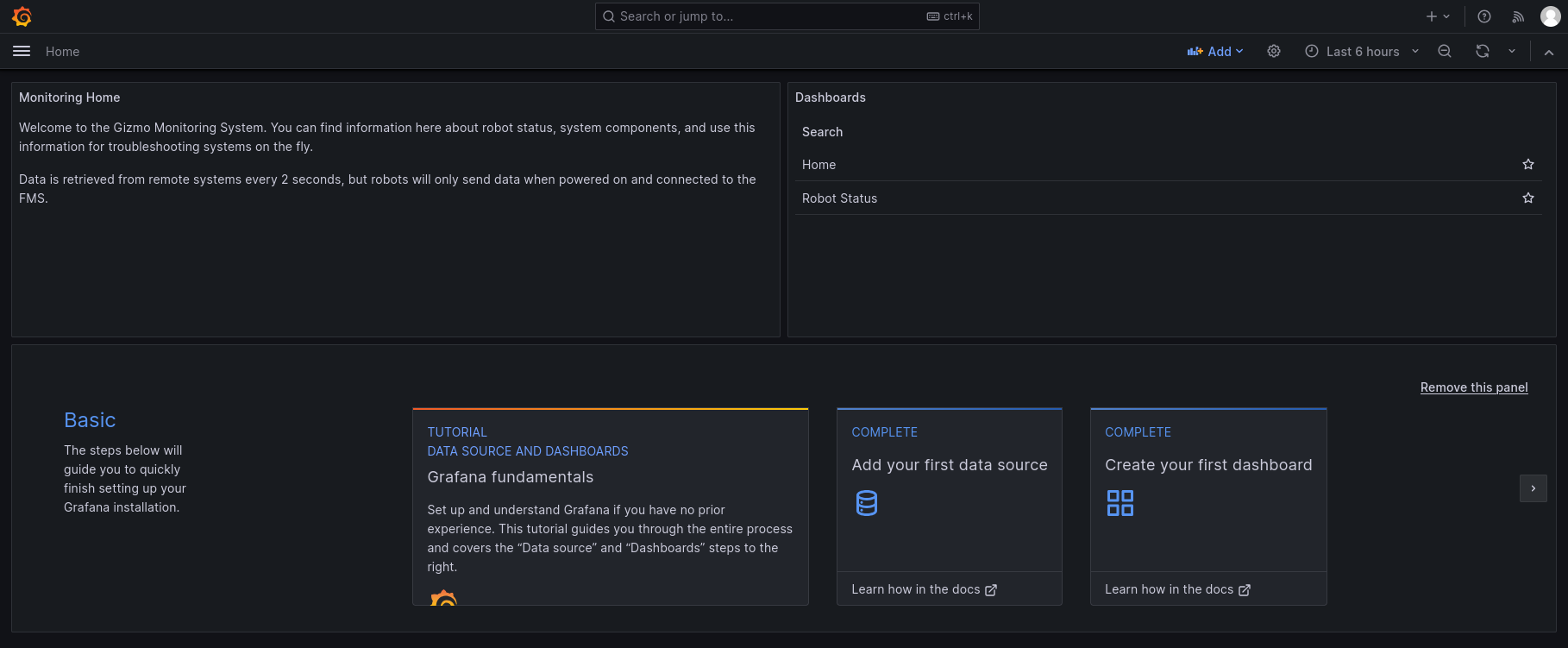
Click on the "Robot Status" item in the right column to access the robot status dashboard. The dashboard will look similar to this example:
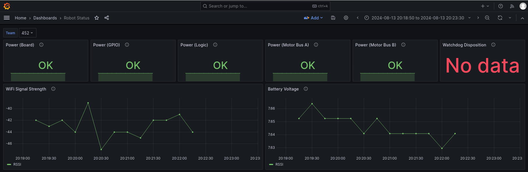
The dashboard provides information on a single robot at a time. The top row shows the status of the various power systems on the robot, and the hardware watchdog if enabled. The graphs in the second row show the strength of the network connection and the battery voltage being supplied to the Gizmo.
note
The Received Signal Strength Indicator (RSSI) value is presented using the standard dBm unit. This means that numbers closer to zero are better (the value is presented as a negative number).
What can you DO with the metrics?
The metrics presented allow you to answer questions about things like if a signal drop out was due to low battery, if a Gizmo reported a tripped polyfuse, or if the wireless network signal is degraded below a point of usability.
tip
The metrics are stored in a Prometheus instance on the FMS. Prometheus and Grafana usage are far far beyond the scope of this manual, but these are industry standard technologies for metrics reporting and visualization. You can create your own custom dashboards that show information in a way that makes sense to you!
Programming the Gizmo
The Gizmo is part of a mechatronics platform. This means it combines electronics and mechanical systems. While there are a lot of clever things you can do with pure electronics, most systems in modern times will include a programmable microcontroller to allow for advanced functionality that would be cumbersome to implement entirely in hardware. The Gizmo is no different and includes a processor dedicated to running user programs.
This section will provide an overview of the various languages and options available for programming the Gizmo. If you don't want to write your own programs, a selection of example code is available for the Arduino environment which can get you quickly up and running with a default configuration.
Programming Languages
Just like languages that people speak, computers speak languages too. These programming languages are used to provide specific instructions to the computer for what you want it to do, how you want it to do it, and what to do if things go wrong. The Gizmo's User Processor is a Raspberry Pi Pico microcontroller which can be programmed in a variety of languages.
The Gizmo team provides explicit support for some of these languages with pre-fabricated support libraries, documentation, and a decent idea of what may have broken when you reach out for help. If you don't like any of the languages that we've chosen to support, it doesn't mean you're out of luck! The Raspberry Pi Pico is based on an ARM Cortex-M0+ processor which has broad support across many popular and niche programming languages. If you want to use a different language than what we've provided, we'd love to see what you come up with! For more information on how to do that, see adding a new language.
For using an existing language, there's several choices to choose from. See below for a list of available options, and consider trying several before you decide which one is right for you.
Arduino
Arduino is an integrated system comprising an Integrated Development Environment (IDE), compiler, linker, and vast selection of libraries. The firmware for the System Processor was developed using frameworks provided by the Arduino ecosystem.
Programming with the Arduino environment is done using the C programming language, though it is also possible to use C++ for additional capabilities. Arduino is a text based environment that runs on your computer and produces a software image that gets installed onto the Gizmo. While often positioned as an advanced language, C does not have to be.
The Gizmo team recommends using Arduino if you have existing experience writing software, or require the highest performance in your programs.
Circuit Python
Python is an extremely popular language for building programs quickly as well as small tools. Python is an interpreted language, so it won't go as fast as a compiled language like C, but if you don't need raw speed its a great choice to get up and running quickly. Circuit Python is a dialect of Python that is built specifically for microcontrollers such as those used on the Gizmo. Circuit Python also has a rich suite of documentation and activities maintained by its sponsor, Adafruit.
Circuit Python is a text based environment which does not require any special tools on a computer to use, you can even write your code using Notepad, though the Gizmo team recommends you use a more powerful editor such as Notepad++ or Visual Studio Code for Python.
The Gizmo team recommends Circuit Python for users that have some understanding of how programs work, but don't want to deal with the more rigorous requirements of programming in C. Python is a great choice for first time programmers as well as its used in a number of introductory curriculums ranging from 6th grade through to the collegiate level.
Microblocks
Microblocks is a drag-and-drop programming environment reminiscent of the Scratch programming language. This programming language requires nothing more than a browser to get started as the entire environment runs as a web-page. Do note that Google Chrome is required.
The Gizmo team recommends Microblocks for anyone who's never written a program before, or environments where students writing code may not be proficient with touch typing.
Adding Support for a New Programming Language
Want to program your Gizmo in a language that we don't currently support? You're in the right place! Adding support for new languages can broadly be split into two categories depending on if a toolchain already exists or not. A toolchain is just support for the Raspbery Pi Pico's ARM Cortex-M0+. You can check if your language supports this or not by seeing if its already possible to program the Raspberry Pi Pico.
While its possible to do the end-to-end development of a language support package in a relatively short time span (the Gizmo Team wrote most of the language support available today in about 2 weeks), we don't recommend you do this during a competition season.
Toolchain Exists
If a toolchain exists, you only need to write a small amount of code that allows your program to talk to the System Processor. For reference, the entire library that supports the Arduino environment is less than 200 lines of code.
Refresh your understanding of the architecture of the Gizmo. The library you are going to write will need to communicate using the I2C protocol to the System Processor and then decode the responses into a format that will be useful for your program.
You can check the exact formats of data by reviewing the firmware source code. You'll need to implement the otherside of the wireRespond function to create an I2C/Wire request, send it, and then unmarshal the data that you get back.
Lets look at the wireRespond function a little more closely:
void wireRespond() {
    byte toSend[18] = {
    cstate.Axis0,
    cstate.Axis1,
    cstate.Axis2,
    cstate.Axis3,
    cstate.Axis4,
    cstate.Axis5,
    cstate.Button0,
    cstate.Button1,
    cstate.Button2,
    cstate.Button3,
    cstate.Button4,
    cstate.Button5,
    cstate.Button6,
    cstate.Button7,
    cstate.Button8,
    cstate.Button9,
    cstate.Button10,
    cstate.Button11,
  };
  Wire1.write(toSend, 18);
}
You can see that all this function does is compress the axis and button data into an array and then write it to the I2C bus. This is a very simplistic protocol and doesn't include any error handling or data framing. This allows it to be extremely portable across languages, and since this data can always be re-requested if a read fails doesn't represent too much risk.
To implement support in your own language, you'll need to write code that performs the inverse of the wireRespond function by creating a request and sending it, then unpacking the data that you get in return. Here's what the refresh function looks like from the ArduinoGizmo library.
void Gizmo::refresh() {
  // The wire format of the Gizmo processor-to-processor interconnect
  // is the classic "bag of structs" variety, which makes it easy to
  // interact with from a variety of languages.
  size_t amountRead = Wire1.requestFrom(GIZMO_ADDR, sizeof(_state));

  if (Wire1.available() >= sizeof(_state)) {
    Wire1.readBytes(reinterpret_cast<uint8_t*>(&_state), sizeof(_state));
  } else {
    _state.Axis0 = 127;
    _state.Axis1 = 127;
    _state.Axis2 = 127;
    _state.Axis3 = 127;
    _state.Axis4 = 127;
    _state.Axis5 = 127;
    _state.Button0 = false;
    _state.Button1 = false;
    _state.Button2 = false;
    _state.Button3 = false;
    _state.Button4 = false;
    _state.Button5 = false;
    _state.Button6 = false;
    _state.Button7 = false;
    _state.Button8 = false;
    _state.Button9 = false;
    _state.Button10 = false;
    _state.Button11 = false;
  }
}
The _state variable is defined elsewhere by the following definition:
struct CState {
  byte Axis0;
  byte Axis1;
  byte Axis2;
  byte Axis3;
  byte Axis4;
  byte Axis5;

  byte Button0;
  byte Button1;
  byte Button2;
  byte Button3;
  byte Button4;
  byte Button5;
  byte Button6;
  byte Button7;
  byte Button8;
  byte Button9;
  byte Button10;
  byte Button11;
};

CState _state;
Because we know that we want to read the amount of data required to fill the CState structure, we can tell the Wire library to read that many bytes. If the number of bytes read doesn't match, then we provide neutral values instead of whatever got read to prevent any runaway robots. Once we're happy that the right amount of data was read, we perform a reinterpret_cast which tells the processor that we want it to take the raw information as a series of ones and zeros and reintepret it as the given structure. In this case, the CState structure that contains all the button and axis information.
The ArduinoGizmo library includes helpful functions to fish values out of the state structure, but this is not strictly required. You've now seen what it takes to add support for the Gizmo to a new language by writing code that talks to the System Processor. This is a relatively straightforward process, but if you get stuck you can always reach out and ask for review of your code.
Toolchain Does Not Exist
Unfortunately if a toolchain from your chosen language does not exist for the Raspberry Pi Pico you're in for an uphill battle. At minimum, you'll need to implement the compiler backend, the low level board support package, and I2C peripheral drivers in your language of choice, all of which is beyond the scope of this document. Still feel free to reach out and if its a language with sufficient interest, the Gizmo Team may be able to help you build some of this support.
Arduino
Arduino refers to a programming environment based on the Wiring framework, and used by hobbyists, industry, and education. Arduino code is typically developed using the Arduino IDE.
The IDE looks like this:
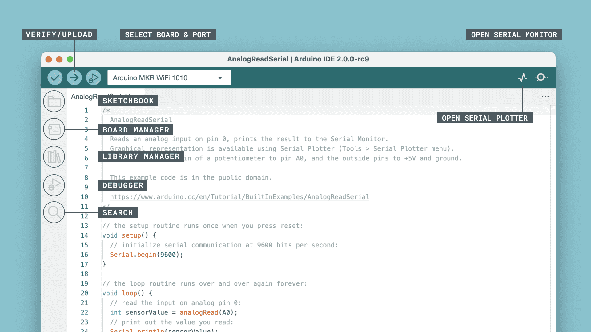
For comprehensive documentation of the IDE and the Arduino ecosystem, consult the Arduino IDE Guide.
This is a text-based choice in which you will write C and C++ programs to power your creations.
Setup
Programming with the Arduino environment will require the Arduino IDE to be installed and configured. This setup will involve installing the Arduino IDE itself, installing the Board Support Package (BSP) and installing the Gizmo-specific libraries. This process takes about 15 minutes on a modern computer with typical broadband internet.
tip
If you're performing this process on Windows, the Gizmo CLI can actually install everything fully automatically.
Just invoke gizmo.exe arduino install followed by gizmo.exe arduino setup and the IDE, support packages, and Gizmo libraries
will be installed for you. This is the recommended path for
institutional admins to deploy as well since it can be automated
with a relatively simple GPO.
Installing the IDE
Start by installing the latest Arduino IDE for your operating system. You can find the latest installers on this page. In the blue sidebar of the first card, select the right package for your computer.
Once you have installed the IDE, open it and proceed to install the Raspberry Pi Pico plugin.
Installing the Raspberry Pi Pico Support Package
The Raspberry Pi Pico requires an additional package that contains compilers, libraries, and other supporting components. These packages are usually referred to as Board Support Packages (BSPs). Detailed installation instructions are available from the upstream documentation. Here is an abridged version:
-
Open the Arduino IDE
-
Open File > Preferences
-
In the settings tab, add the following URL in the "Additional Boards Manager URLs":
https://github.com/earlephilhower/arduino-pico/releases/download/global/package_rp2040_index.json
-
Hit "OK" to save the URL.
-
Open the boards manager from Tools > Boards > Board Manager
-
Search for "Pico" and install the entry by Earle F. Philhower, III.
Install the Gizmo Libraries
The Gizmo makes use of a custom library to provide aliases for all the pin names and to provide a means of retrieving information from the system processor.
To install the library, follow these steps:
- Open the Arduino IDE
- Open Tools > Manage Libraries...
- Search for "Gizmo"
- Install the entry by M. Aldridge. Unless you have received other instructions, install the most recent version.
Hello World
Lets start off with a really simple program. It won't use the gamepad, gizmo tool, or any other hardware. This program will introduce the concepts of the loop(), setup(), pinmode(), delay(), digitalWrite(), and digitalread() primitives which are fundamental to more complicated programs.
Within the Arduino language specification there are several important functions. Lets look at each one now:
-
pinMode(pin, <INPUT|OUTPUT>)- This function tells the processor which way we want signals to go on a particular pin. In general pins that you want to read status from are inputs and pins you want to export a state to are outputs. -
delay(millis)- This function causes the processor to wait an amount of time before proceeding to the next instruction. You can specify the amount of time to wait in milliseconds. Recall that 1 second is composed of 1000 milliseconds, so if we want our program to wait for 1 second, we would writedelay(1000);. -
digitalWrite(pin, <HIGH|LOW>)- This function sets the value of a digital I/O pin. Thepinrefers to a pin number, or a named pin constant as provided by the Gizmo library. The value the pin will be set to should be eitherHIGHorLOWreferring to whether or not the pin should source current or sink it. Phrased differently, setting the pinHIGHwill raise the voltage present at the pin to a nominal logic level of 3.3v. Setting itLOWwill ground the pin to a nominal voltage of 0v. -
digitalRead(pin)- This is the inverse of thedigitalWrite()function and reads the value of a pin. If the pin has voltage being applied to it, the function will return the special symbolHIGH. In all other cases, the return value will beLOW. Using an external circuit to provide either voltage or ground to a signal pin can be a powerful tool to detect the state of a mechanism that has 2 possible states, such as a limit switch.
In addition to the above functions, most Arduino programs will make use of two special functions that are part of the Arduino frameowrk. These are the setup() and loop() functions. The setup() function is fairly intuitive based on the name, as you might guess, it is where you put code that is going to perform an initialization task to prepare for further work to be done.
The loop() function is slightly more complicated, and is the primary entrypoint to code you write. This means that once the Arduino framework has performed global initialization, processed all the functions that you defined in setup() and processed any internal housekeeping, the loop() function will be called and, as the name implies it will be called in a loop. This means that code you put in this loop function will be run in a repeated nature until you remove the power from the Gizmo.
note
In these examples, you'll see the keyword void used in front of
setup() and loop(). This is called a type and instructs the
compiler that processes our program that these functions won't
return any values. Learn more about the void keyword
here.
Lets put this into practice and write a program that will blink the onboard status LED that's part of the User Processor. First, we'll write the setup() function.
void setup() {
    pinMode(LED_BUILTIN, OUTPUT);
}
Above we learned that the pinMode() function takes a number as its first argument, but here we passed the symbol LED_BUILTIN, how does that work? Within the Arduino world lots of boards have a small light built in for user applications. You can blink this light, use it to indicate a status, or ignore it. To make these lights easy to use, they are connected to a pin that has a name, in this case called LED_BUILTIN.
Next, lets write the loop() function that will turn the light on, wait 1 second, then turn it off again and wait another second. This will result in an even blinking pattern where the light is on half the time and off half the time.
void loop() {
    digitalWrite(LED_BUILTIN, HIGH);
    delay(1000);
    digitalWrite(LED_BUILTIN, LOW);
    delay(1000);
}
warning
While the processor is waiting it can't do anything else! This can be okay in some circumstances, but is usually not what you want to do because it means that other tasks such as maintaining motor controllers, reading sensor values, or processing gamepad inputs won't be processed.
Altogether, our program looks like this:
void setup() {
    pinMode(LED_BUILTIN, OUTPUT);
}

void loop() {
    digitalWrite(LED_BUILTIN, HIGH);
    delay(1000);
    digitalWrite(LED_BUILTIN, LOW);
    delay(1000);
}
You can compile and upload this program to the Gizmo by plugging a USB cable into the right hand USB port on the top of the board and clicking the "Upload" arrow in the Arduino IDE. Note that you may need to select the serial port in the Tools menu if it was not automatically detected.
This program works, but can we improve it? We know that if the light is on we want to turn it off and if its off we want to turn it on. Logically, we want the inverse of whatever state the light is in currently. Lets refactor our loop to use this knowledge by reading the value of the light and inverting it.
void loop() {
    digitalWrite(LED_BUILTIN, !digitalRead(LED_BUILTIN));
    delay(1000);
}
Our 4 line loop is only 2 lines long now, that's a 50% reduction in code to achieve the same result! How does it work though? Recall that the digitalWrite function needs to know whether or not we want to drive the pin to a HIGH or LOW state. Further recall that the digitalRead function checks what state a pin is in and reports that as a HIGH or LOW status. Since we want the logical opposite of whatever state the LED is in, we can use the logical ! operator which means "NOT".
If we were to read out the line in English we might say it like so:
Perform a digital write to the pin connected to the LED with the opposite value of the pin connected to the LED.
This works well for our blinking light because we don't care what state the light is in each second, we just want it to transition to whatever state its not in now. This also reveals part of how HIGH and LOW work, since the ! operator only makes sense to use on boolean values. The HIGH and LOW names are just synonyms for true and false.
Try changing the delay statements or creating patterns with different combinations of delays and HIGH/LOW commands to get a better understanding of what each change effects.
Recap
In this program we learned about the setup() function, the loop() function, and functions related to input and output of digital values. We also learned how to combine the results of a digital read with a digital write to compact our code into fewer lines.
Spin a Wheel
In the previous tutorial we used some simple functions to turn a light on and off. Lets use some more advanced code to now control a motor. In this program we'll make use of a VEX MC-29 motor controller. These motor controllers use a Pulse Width Modulation signal to determine direction and magnitude of the motor rotation they control.
To control the MC-29, we'll make use of a software library. A software library is a collection of code written by someone else which is packaged up into a format that allows it to be re-used. Libraries are a core component of most programs and encapsulate standard functionality that is abstract enough to be useful across multiple programs.
For this program, we're going to use the Servo library to make the motor slowly ramp from spinning in one direction to spinning in the other direction. Full documentation for the Servo library can be found here.
Why are we using a library for Servos to control a motor? Servos are just a special kind of motor that are aware of how far they've spun. While this is really useful for a lot of applications where absolute positioning is required, like the fuel gauge in a car, its less useful when we want a continuous source or rotation like a DC gear motor. In these cases we can use a Continuous Rotation Servo which takes the same input signals as a servo, but rather than moving to a particular location in absolute terms, we control the rate of rotation in relative terms.
To start our program, we'll need to tell the Arduino compiler that we intend to use the Servo library, and that we want to connect a servo compatible device to motor port 1 on the Gizmo. Motor port 1 is the lowest connector on the right vertical grouping of connectors. The signal wire (white) for the MC-29 should be on the left side of the connector when it is plugged in.
#include <Servo.h>
This tells the compiler that we want to include the Servo library and make its functions available to the rest of the program. To use the names for ports rather than the numbers, we'll also need the Gizmo's library which provides these names. Include it in the same way:
#include <Gizmo.h>
Now that we have the servo library, we can make use of it and define a motor to use later:
Servo myMotor;
Just as in our blinking light program, we'll perform setup tasks in the setup() function:
void setup() {
    myMotor.attach(GIZMO_MOTOR_1);
}
This code tells myMotor to attach to and take control of the pin that the motor is connected to. On the Gizmo we name these pins so that its easier to understand what they're connected to, and to make code work across multiple different generations of the Gizmo's physical hardware. In this case, we're using the #1 motor port.
Lets make the motor move. We'll do that with 2 loops, one to ramp from full reverse slowly to full forward, and one to go from full forward to slowly full reverse. Since we want to output a range of values from one extreme to another, we'll use a for loop inside our larger loop() function.
A for() loop has the following syntax:
for(initialization, condition, increment)
You can read the full documetation of the for construct here, but the abridged version is as follows: The initialization code happens exactly once on the first trip through the loop. The condition is checked every time and has to evalute as a true expression to continue running the loop, and the increment happens after each trip through the loop. This is pretty abstract, so lets write a loop and see how it works:
for (int i=0 ; i<180 ; i++) {
    myMotor.write(i);
    delay(20);
}
This creates an integer variable called i and sets its value to 0, then says that this loop will run as long as the value of i is less than or equal to 180. Finally, each time through the loop we'll increase the value of i by one. The i++ is a more compact way of writing i = i + 1, but it does the same thing. Then, each time through the body of the loop (the indented part), we tell the motor to change speed to the current value of i and wait 20 milliseconds. We have to wait because the motor has some inertia and needs time to accelerate.
You might notice that we're incrementing from 0 to 180, and this is going from full speed in one direction to full speed in another. The Servo library uses a range from 0 to 180 to express output values because most standard servos can sweep through 180 degrees with a centerpoint at 90 degrees. Since our servo is a continuous rotation motor, this means that we have 90 steps of speed in one direction for values ranging from 0-89, then a stopped motor at a value of 90, then another set of steps in the other direction ranging from 91-180.
Lets put all of what we've learned together to write the whole program. You'll notice that for sending the motor the other way its the same loop body, but the numbers at the top are reversed so the loop goes from 180 to 0 now.
#include <Servo.h>
#include <Gizmo.h>

Servo myMotor;

void setup() {
    myMotor.attach(GIZMO_MOTOR_1);
}

void loop() {
    for (int i=0 ; i<180 ; i++) {
        myMotor.write(i);
        delay(20);
    }
    for (int i=180 ; i>0 ; i--) {
        myMotor.write(i);
        delay(20);
    }
}
Each time through loop() this code will spin the motor from one speed extreme to another, reversing the direction in the middle.
note
Motors take a lot of power. Way more than can be safely pulled out of the USB ports on your computer. To run this program, you'll need to have a battery conected to your Gizmo board. Check the instructions around the Main Power Connector for more information on connecting this cable.
Recap
In this program we learned about libraries and used the Servo library to control a motor. We also learned about how to use for loops to increment and decrement a value in a cycle.
Gizmo Library
In the last tutorial we used the Servo library to control a motor. The Gizmo itself has a library that we referenced in the previous tutorial, but didn't dive into it deeply. Lets do that now and learn about what functions the Gizmo library includes.
Named Constants
The Gizmo library provides special names for a number of different items to make referring to them more intuitive and clearer. This isn't an excuse to not document your code, however, and you should still take time to produce thoughtful comments to help others and your future self understand what your program does!
The named constants that the <Gizmo.h> library provides can broadly be subdivided into 2 categories: items related to the gamepad, and items related to the Gizmo board itself.
Gamepad Values
On the recommended Logitech F130 gamepad, there are 2 joysticks, 1 POV hat, 2 triggers, 2 shoulder buttons, 4 thumb buttons, and 2 special buttons in the center area of the controller. If you push down on the joysticks themselves, you'll hear and feel a satisfying click because the joysticks are buttons too!
The gamepad has the following named axes. Axes values range from 0 to 255, with the neutral position at 127. The joysticks have a deadband, sometimes called a "detent" around this value to ensure that even with small manufacturing differences between gamepads when you let go of the joysticks they self-center and return to the 127 value.
GIZMO_AXIS_LX- Left stick X-AxisGIZMO_AXIS_LY- Left stick Y-AxisGIZMO_AXIS_RX- Right stick X-AxisGIZMO_AXIS_RY- Right stick Y-AxisGIZMO_AXIS_DX- D-pad/POV hat X-Axis. This will "snap" between 0 and 255.GIZMO_AXIS_DY- D-pad/POV hat Y-Axis. This will "snap" between 0 and 255.
Similarly, all of the buttons are named as well:
GIZMO_BUTTON_X- X buttonGIZMO_BUTTON_A- A buttonGIZMO_BUTTON_B- B buttonGIZMO_BUTTON_Y- Y buttonGIZMO_BUTTON_LSHOULDER- Left shoulder buttonGIZMO_BUTTON_RSHOULDER- Right shoulder buttonGIZMO_BUTTON_LT- Left triggerGIZMO_BUTTON_RT- Right triggerGIZMO_BUTTON_BACK- Center back buttonGIZMO_BUTTON_START- Center start buttonGIZMO_BUTTON_LEFTSTICK- Left joystick stalkGIZMO_BUTTON_RIGHTSTICK- Right joystick stalk
Gizmo Port Values
The Gizmo has a number of I/O interfaces for your use. These are divided up into names based on functions. The names correspond to the names on the diagram below:

For motors, there are port names GIZMO_MOTOR_N where N is a number ranging from 1-8. On newer boards with dedicated servo ports, N ranges from 1-4 with an additional set of names GIZMO_SERVO_N to identify servo ports 1-4.
For digital I/O, the GPIO ports are numbered from 1-8, and can be referred to as GIZMO_GPIO_N where N is the port number you wish to address.
The Gizmo contains 3 analog to digital converters, that allow you to sense an analog value such as one that varies based on a potentiometer reading. These ports are identified as GIZMO_ADC_N where N is between 1-3.
warning
The analog ports must not be connected directly to the battery as doing so would harm the voltage measuring circuitry. Use only the power provided on the ADC port as the voltage reference!
For serial functions, the UART port is named with two special names for the TX and RX pins. These names are GIZMO_UART_TX and GIZMO_UART_RX. UART is a somewhat antiquated term to refer generally to a serial port. When looking at the above image, the pin order is top to bottom, ground, TX, RX, 3.3v.
Finally, the neopixel header where you can connect programmable LEDs is identified by the symbol GIZMO_NEOPIXEL.
Functions
The <Gizmo.h> library provides more than just names for pins. It provides a convenient way to interact with the field control server running on a driver station or full field management system. Using this functionality is very similar to using the Servo library. First we tell the compiler that we want to make use of the library in our program:
#include <Gizmo.h>
Then, at the top of the program outside the setup() and loop() functions we create a named instance of the library to use. For convenience, we'll call it gizmo in these docs, but you are free to name it any valid C symbol name.
Gizmo gizmo;
Then, in the setup() function, we can run the begin() funcion of the library to connect to the System Processor.
setup() {
    gizmo.begin();
}
Each time through the loop() function we need to refresh the data from the System Processor so that we can use any values that have changed. This is done by calling the refresh() method.
gizmo.refresh();
Finally, we can use the getButton(id) and getAxis(id) methods to retrieve the values of buttons and axes, respectively. The id parameter expected by these functions is one of the named constants described earlier
The button values are returned as boolean values of either true or false and can be used in conditional statements or other control structures. The axis information is returned as an unsigned 8-bit number (byte) ranging from 0-255, with the neutral position at 127.
Recap
We learned that the Gizmo library provides names for pins on the physical board as well as names for the various buttons and axes on the gamepad. We then learned that there are functions for accessing this information.
Drive a Robot
So far with the Arduino environment we've learned about the basics of the framework, how to use libraries, and about the <Gizmo.h> library. Now we can put it all together to use the Gizmo board to drive a 2 wheeled robot. This robot will use tank/skid steering, and will receive its control signals from a practice field.
Writing the Code
To drive the robot, we'll make use of a sample program that comes with the ArduinoGizmo library. In the Arduino IDE menu bar, select the BasicRobot example code by opening the following menus:
File > Examples > Gizmo > BasicRobot
You may need to scroll down in the Examples menu to get to the Gizmo option, it will be near the bottom. With the comments removed, the program that will drive the robot is as shown:
#include <Servo.h>
#include "Gizmo.h"

Servo DriveL, DriveR;
Gizmo gizmo;

void setup() {
  gizmo.begin();

  pinMode(GIZMO_MOTOR_1, OUTPUT);
  pinMode(GIZMO_MOTOR_2, OUTPUT);

  DriveL.attach(GIZMO_MOTOR_1);
  DriveR.attach(GIZMO_MOTOR_2);

  pinMode(LED_BUILTIN, OUTPUT);
}

void loop() {
  digitalWrite(LED_BUILTIN, !digitalRead(LED_BUILTIN));

  gizmo.refresh();

  int targetL, targetR;
  targetL = map(gizmo.getAxis(GIZMO_AXIS_LY), 0, 255, 0, 180);
  targetR = map(gizmo.getAxis(GIZMO_AXIS_RY), 0, 255, 0, 180);

  DriveL.write(targetL);
  DriveR.write(targetR);

  delay(20);
}
This program is only 31 lines of code and it can drive a robot. Now, this robot doesn't do much, but it is a great starting point to extend further. As written, this code expects a left and right drive motor to be attached to the first 2 motor ports. It also toggles the built-in LED to show that the program is running and hasn't frozen.
For more detail about what each component does, the example code in the Arduino IDE is heavily commented with descriptions for each component.
The one portion of this code that hasn't been shown yet in any of our previous programs is the map() function. These two lines do a really important task:
targetL = map(gizmo.getAxis(GIZMO_AXIS_LY), 0, 255, 0, 180);
targetR = map(gizmo.getAxis(GIZMO_AXIS_RY), 0, 255, 0, 180);
The joystick axis values range from 0 to 255, but the motor control range is from 0 to 180. The mapping between these two values is just a linear proportion, but the map() function saves the effort of writing out this proportion. It takes an input value, in this case the result of the gizmo.getAxis() function, an input range (0-255), and an output range (0-180) and performs all the math in the background to transpose from one range to the other. The output of these computations is saved to temporary values to contain the target left and right motor speeds, but we could just as easily have condensed the map function into the write() for the motors.
To drive a robot around using this code, upload it to the Gizmo and make sure you have a practice mode running. You should see the 3 status LEDs on the Gizmo indicate green on top for a stable wireless connection, then a blinking white light in the middle to indicate the practice field is connected, and the bottom status LED will change colors based on the battery voltage. Once the middle LED starts blinking white, try pushing on the joysticks and the motors should respond. If one motor spins in the wrong direction, you can either fix this problem in software by inverting the range for that motor, or you can just swap the wires around to physically reverse the polarity of the motor.
Recap
In this tutorial we loaded the BasicRobot demo code and drove a robot around using the gizmo practice field. From here you can use the BasicRobot program as a starting point to make your own additions. Try adding another motor to control a manipulator, consider adding servos for movement, or try reading limit switches to navigate by bumping up against walls fully autonomously.
Remember you can always learn more about the Arduino environment on the Arduino Website, or if you get stuck, you can get help.
Circuit Python
Circuit Python is a dialect of the Python programming language targetting microcontrollers. It is maintained by Adafruit.
The programming experience with Circuit Python is based on writing and copying Python source files to the device through your computer's file system. This means you can write Circuit Python code in any text editor. With that said, there is an ecosystem of recommended tools that make the process even easier.
Documentation for the Circuit Python language and core libraries are available at https://docs.circuitpython.org/.
Adafruit provides excellent, beginner-focussed documentation on how to use Circuit Python at https://learn.adafruit.com/welcome-to-circuitpython.
Setup
While no specific editor or tools are required for using Circuit Python, this documentation will make use of the recommended tools, namely the Mu editor and CircUp library management tools.
Installing the Circuit Python Runtime
In order for your microcontroller to be able to use Circuit Python, you have to install board-specific firmware.
Download the Circuit Python v9.0 runtime (.uf2 file) for the Raspberry Pi Pico from https://circuitpython.org/board/raspberry_pi_pico/.
note
Only versions within 9.0.X (ie. 9.0.4) have been tested with the Gizmo. Newer or older versions may not work.
Hold your Gizmo's student processor BOOTSEL ("Boot Select") button down while connecting the USB programming cable to your computer. Once you've connected the cable, release the BOOTSEL button.
You should now see an external drive on your computer called "RPI-RP2".
Copy the .uf2 file you downloaded to the "RPI-RP2" drive.
Your device will automatically reboot and reconnect as a new drive called "CIRCUITPY".
warning
Each time you reinstall the CircuitPython runtime, any programs on your Gizmo will be erased.
tip
If your Gizmo ever gets stuck in a way that prevents you from saving new Circuit Python code to it or if it stops showing up as the CIRCUITPY drive when you connect it, you may need to re-install the runtime by following the above steps again.
Installing the Mu Editor
Mu is a simple Python editor and is the recommended editor for Circuit Python code.
If you would like more information about using the Mu editor, including an introduction to the user interface, checkout the Mu tutorial articles.
-
Download and run the installer for your operating system from the Mu download page.
-
When prompted for what mode to run Mu in, make sure to select Circuit Python.

- Mu tries to automatically connect to Circuit Python devices attached to your computer. By default, when you save the code you're writing in Mu, it will save directly to your Circuit Python device. If it can't find one, it will show you this warning explaining where the code you write will be saved on your computer.

Installing the CircUp Library Manager
Like your code, libraries for Circuit Python devices are managed by copying files onto the CIRCUITPY drive. While this can be done manually, it involves quite a bit of downloading files from different websites and extracting zipped folders. The CircUp tool manages these processes for you to keep your installed libraries up to date.
Adafruit provides detailed installation instructions for Windows, Mac, and Linux. You can find these instructions here. Specifically, follow the steps in the "Prepare for Install" and "Install CircUp" sections.
Installing the Gizmo Circuit Python Library
To install the Gizmo Circuit Python library with the CircUp tool, run these commands in the terminal on your computer:
-
Add the bundle to your local list.
$ circup bundle-add gizmo-platform/CircuitPython_Gizmo- Install the module to your connected device.
Shell $ circup install circuitpython_gizmo
- Install the module to your connected device.
Hello World
Let's begin writing some simple Circuit Python code for your Gizmo. A common beginner program when working with microcontrollers is blinking an LED. Conveniently, the Gizmo's student processor has an LED built in to it. This lesson will introduce some of the most common Circuit Python modules and will walk you through creating a program that blinks the built in LED. This code won't require any extra hardware plugged into your Gizmo. You will only need the Gizmo itself and the USB programming cable.
Connect the USB programming cable to the student processor on your Gizmo and plug it into the computer.
What is a module?
When writing any kind of software, it is helpful to reuse code that other people have written. They've already put in the work to make sure it works correctly! A "library" is collection of helpful code that is shared between projects. In Python, every library is made up of one or more "modules." A module is a single file of Python code that defines useful objects or functions for other Python files to use.
In order to use the tools a module provides, we have to import it into our script. This is done with an "import statement". These are usually at the top of a Python script and look like this:
import module_name
You can learn more about the details of Python modules here. For now, the important thing to understand is that we use import to pull in useful code from another file.
The board Module
The board module is the Circuit Python module that gives constants for the pins and other features your board has. The contents of the board module are specific to the device running the code.
For this tutorial, we'll be using the board.LED pin constant. This "pin" isn't one of the pins that run along the edge of the board. Instead, it is wired up to control the LED built into the Raspberry Pi Pico.
The digitalio Module
The digitalio module gives us control over the digital input/output pins available on a microcontroller. API documentation for this module is available here.
With this module, we can use the DigitalInOut class to control pins.
pin = digitalio.DigitalInOut(board.LED)
pin.direction = digitalio.Direction.OUTPUT

pin.value = True  # Set the pin output high
pin.value = False  # Set the pin output low
This code creates a DigitalInOut object to control the built in LED pin. Because we want to control the voltage of this pin with our code, we set the direction to OUTPUT. If we were instead connecting a sensor we wanted to measure from, we would use the INPUT direction. Finally, to change the output voltage on this pin, we set the value property to either True or False, which are translated into a high signal (3.3 volts) and low signal (0 volts) respectively.
The time Module
The time module provides a handful of time and timing related functions. API documentation for this module is available here.
In this tutorial, we'll be using time.sleep(). This function pauses the program for the number of seconds you give the function. For example, time.sleep(1.0) pauses the code for one second.
warning
When the program is sleeping, it is not doing other work like checking sensors or responding to gamepad inputs. This might not always be what you want, so pay attention to when you add sleeps to your code and how long they are.
Basic Program Structure
Circuit Python programs are scripts where each line of code is executed in order from the top of the file to the bottom. Technically, an empty file is a valid Circuit Python program that does nothing. Most Circuit Python code follows a common pattern where everything the program needs is set up at the start and then a loop runs repeating the same set of instructions forever until the device is turned off. Here's what that looks like in code:
# Imports at the top to grab the modules the code uses

# Setup code that runs once at the start

while True:
  # Instructions to repeat forever
  pass
note
Lines that start with a # symbol in Python are comments. They are for adding notes to our code that the computer won't try to read.
note
The pass keyword lets us write empty loops or functions without
breaking Python's rules about indentation. It's common as a placeholder
when writing code.
Blinking an LED
No we can put everything from the above sections together into a program the turns the built in LED on an off.
First, we need to import the modules our code will use.
import board
import digitalio
import time
Then, in the setup part of our program, we'll create the DigitalInOut object for controlling the LED and set it in the output direction.
led = digitalio.DigitalInOut(board.LED)
led.direction = digitalio.Direction.OUTPUT
Finally, our program's loop will turn the LED on, wait some time, turn the LED off, and wait some more time.
while True:
  led.value = True
  time.sleep(1.0)
  led.value = False
  time.sleep(1.0)
Altogether, our program looks like this.
import board
import digitalio
import time


led = digitalio.DigitalInOut(board.LED)
led.direction = digitalio.Direction.OUTPUT


while True:
  led.value = True
  time.sleep(1.0)
  led.value = False
  time.sleep(1.0)
You can try this code on your Gizmo by connecting the USB cable to the student processor on your Gizmo and saving the code there in the Mu editor. You should see the LED on the student processor blinking.
This program works, but can we improve it? We know that if the light is on we want to turn it off and if its off we want to turn it on. Logically, we want the inverse of whatever state the light is in currently. Lets refactor our loop to use this knowledge by reading the value of the light and inverting it.
while True:
  led.value = not led.value
  time.sleep(1.0)
Our 4 line loop is only 2 lines long now, that's a 50% reduction in code to achieve the same result! How does it work though? Setting the value property of our DigitalInOut object controls the state of the pin. This property also remembers what we last set it to. We invert the old value with the not keyword, which turns False to True and vice versa.
This works well for our blinking light because we don't care what state the light is in each second, we just want it to transition to whatever state its not in now.
Try changing the delay statements or creating patterns with different combinations of delays and True/False commands to get a better understanding of what each change effects.
Recap
In this program we learned about the board, time, and digitalio modules. We also learned the common structure of a Circuit Python program and how to control digital output pins.
The Circuit Python Gizmo Module
In this tutorial, we will introduce the circuitpython_gizmo module and the print function. You will learn how to get input from your gamepad and how to send text back to your computer to help debug your code.
The print Function
When your Gizmo is connected to a computer, your CircuitPython programs are able to send information back to your computer. The messages your Gizmo sends will show up in the "serial" viewer in the Mu editor. Your code sends these messages by calling the print function.
note
"Serial" is a generic term that refers to several different low-level
communication protocols used in electronics. Often this refers to a UART used to communicate between microcontrollers. For our purposes here, the USB connection is emulating a simple "serial" communication protocol.
To use the print function, give it the message you want to send. This can be text, numbers, or variables. The print function is always available, so you don't have to import any modules to use it.
# Sending text
print("Hello from Gizmo!")

# Sending variables
value = 100
print(value)
You can also embed variables into text messages to give more context. Just put an 'f' in front of your message and wrap the variable names in curly brackets. For example:
count = 2
print(f"The count is {count}.")
# This will print "The count is 2."
note
This syntax with 'f' in front of a string is called a "formatted string literal" or f-string for short. You can find out more about f-strings here.
The circuitpython_gizmo Module
The circuitpython_gizmo module gives access to the unique features of the Gizmo. This includes pin name constants and gamepad values. This is all done with the Gizmo class.
import circuitpython_gizmo

# Create a new Gizmo object
gizmo = circuitpython_gizmo.Gizmo()
The Gizmo class has several useful variables and functions. Firstly, it features a number of useful constants for referencing the ports on the Gizmo.
gizmo.MOTOR_N- the nth motor port (1 - 8)gizmo.GPIO_N- the nth gpio port (1 - 8)gizmo.ADC_N- the nth analog port (1 - 3)gizmo.NEOPIXEL- the Neopixel portgizmo.UART_TXandgizmo.UART_RX- the transmit and receive pins for the UART port
Gizmo can also be used to retrieve the gamepad states.
There are six axes available:
gizmo.axes.left_x- Left stick X-axis (0-255)gizmo.axes.left_y- Left stick Y-axis (0-255)gizmo.axes.right_x- Right stick X-axis (0-255)gizmo.axes.right_y- Right stick Y-axis (0-255)gizmo.axes.dpad_x- D-pad X-axis (0, 127, or 255)gizmo.axes.dpad_y- D-pad Y-axis (0, 127, or 255)
There are twelve buttons available:
gizmo.buttons.x- X buttongizmo.buttons.a- A buttongizmo.buttons.b- B buttongizmo.buttons.y- Y buttongizmo.buttons.left_shoulder- Left shoulder buttongizmo.buttons.right_shoulder- Right shoulder buttongizmo.buttons.left_trigger- Left triggergizmo.buttons.right_trigger- Right triggergizmo.buttons.back- Back buttongizmo.buttons.start- Start buttongizmo.buttons.left_stick- Left joystick stalkgizmo.buttons.right_stick- Right joystick stalk
Finally, the refresh function must be called at regular intervals to get the latest information from the system processor. This is usually done towards the start of your program's infinite while loop.
while True:
  gizmo.refresh()
Logging Gamepad State
Let's put everything we've introduced here together in a simple program that counts how many times a button on our gamepad is pressed.
First, import the Circuit Python Gizmo module.
import circuitpython_gizmo
Then, create three variables:
gizmo: aGizmoobject and a counter variablecount: a number that will track how many times the button has been pressedprevious_button_state: a boolean (True/False) that will remember whether the button was pressed in the previous loop iteration
gizmo = circuitpython_gizmo.Gizmo()
count = 0
previous_button_state = False
Next, in a while loop, refresh the Gizmo object to get the latest information.
while True:
  gizmo.refresh()
Still in the loop, check if the A button has been pressed. If it is pressed now and wasn't pressed last time, we know this is the start of a new press and the count should increas by 1.
  if gizmo.buttons.a and not previous_button_state:
    count += 1
    print(f"The button has been pressed {count} times.")
Finally, end the loop (outside of the if) by updating previous_button_state.
previous_button_state = gizmo.buttons.a
The complete program looks like this:
import circuitpython_gizmo

gizmo = circuitpython_gizmo.Gizmo()
count = 0
previous_button_state = False

while True:
  gizmo.refresh()
  if gizmo.buttons.a and not previous_button_state:
    count += 1
    print(f"The button has been pressed {count} times.")
  previous_button_state = gizmo.buttons.a
To run this program, make sure your Gizmo battery is plugged in and the Gizmo is connected to your driver station.
Recap
In this tutorial, we've introduced the circuitpython_gizmo module and the print function. With these new tools, we wrote a program that counts button presses on your gamepad.
Spin a Wheel
In the previous tutorial we used some simple functions to turn a light on and off. Lets use some more advanced code to now control a motor. In this program we'll make use of a VEX MC-29 motor controller. These motor controllers use a Pulse Width Modulation (PWM) signal to determine direction and magnitude of the motor rotation they control.
For this program, we're going to use two new modules: pwmio and adafruit_motor.
The pwmio Module
PWM is a simple way to send an analog signal over a digital pin. It is commonly used for controlling motors, servos, and other actuators. The pwmio module provides the PWMOut class to efficiently generate PWM signals on a pin using our microcontroller's built-in timers. A timer is a dedicated piece of hardware that accurately keeps track of time without the main processor having to think about it. Most microcontrollers use timers to get very accurate PWM signals while the main code can work on other tasks. There are two important values for us to control with a PWMOut object: frequency and duty cycle.
Frequency is the number of times each second that the signal changes from low to high and back to low. This is measured in Hertz (Hz). One Hertz means "once per second."
Duty Cycle is the fraction of the total pulse time where the signal is held high. 0% duty cycle is a signal that is always low. 100% duty cycle is a signal that is always high. 50% duty cyclce is a signal that spends an equal amount of time high and low.
While PWM is an important concept to understand in robotics, we don't need to use it directly for controlling motors. We introduce this module here because it is used by the adafruit_motor module.
API documentation for the pwmio module is available here.
The adafruit_motor Module
The adafruit_motor module provides tools for controlling a variety of types of motors. We will use the adafruit_motor.servo module specifically.
Why would we use a "servo" module for controlling our motors? In our case, it's because they use the same control interface. The Vex MC29 makes our DC gear motors behave like "continuous rotation servos" by using PWM to control them. You have probably seen servo connectors like the ones on the Vex MC29 before. This is a standard style of connector that is very popular for remote control cars and planes. The red and black wires provide power to the servo / motor and the white wire carries a PWM signal to control the servo / motor.
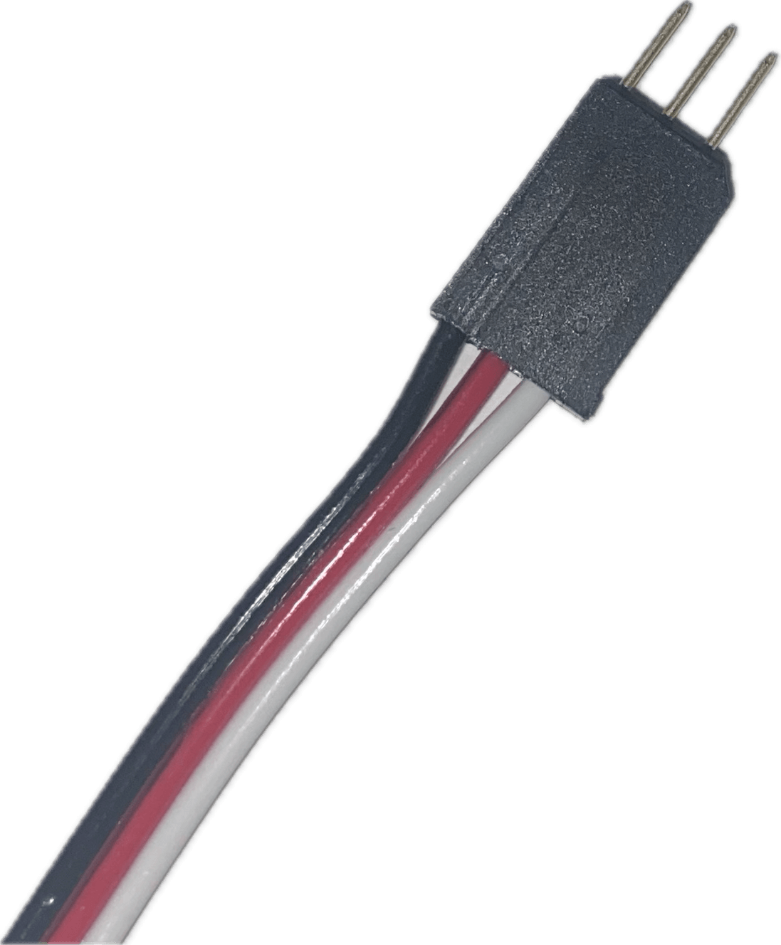
Servos control their position based on the signal they receive. We can control servos using the Servo class in adafruit_motor.servo. It has a property called angle that lets us set the position of the servo. Another property called actuation_range tells the Servo object how far the physical servo is able to move, so the code knows how to convert our angles into PWM signals.
For controlling motors, we can use the ContinousServo class in adafruit_motor.servo. It has a property called throttle which controls the speed of the motor. throttle can be set to any value between -1.0 and 1.0. Positive numbers will make the motor spin one direction and negative numbers will make the motor spin the other direction. Zero throttle will stop the motor.
Both of these objects are created by giving them a PWMOut object connected to a pin. Optionally, you can also tell them the minimum and maximum pulse widths in milliseconds.
API documentation for the adafruit_motor module is available here.
Looping Over Numbers
A common need in programs is looping over a range of numbers. This could be just because we need to repeat some action a certain number of times, or to loop through the elements in a list of items, for example. In Python, we can do this with a for loop and the range function.
A for loop, in Python, runs the body of its loop once for each element in a container. If you give the list of numbers [1, 2, 3, 4], the loop will run four times.
# This loop will run 4 times
for i in [1, 2, 3, 4]:
  # i holds the current element from the list
  print(i)
# This code will output:
# 1
# 2
# 3
# 4
Usually, we don't want to list out each number in the range one by one. Instead, we create a range object. A range object can be created in one of three ways:
# Create a range with the number of values it should hold
# This range will hold the numbers 0 through 9
range(10)

# Create a range with a start and stop value
# The range includes the start value, but does NOT include the stop value
# This range will hold the numbers 5 through 19
range(5,20)

# Create a range with start, stop, and step values
# step controls the difference between values in the range
# A step of 2 means each number will be the previous number plus 2
# This range will hold even numbers from 0 through 98
range(0, 100, 2)
Using a range in a for loop, we can make a loop that runs 10 times:
for i in range(10):
  print(i)
Controlling a Motor With Gizmo
Now let's write a program that controls a motor connected to our Gizmo. This program will run the motor through at different speeds. To get started, connect a motor to your Gizmo using the Vex MC29 motor controller on motor port 1.
To start our program, we'll import the modules we need to use.
import pwmio
import time
import adafruit_motor.servo
import circuitpython_gizmo
For the setup portion of our code, we just need to setup a Gizmo object and an object to control the motor. To make sure we're creating the right kinds of signals for the Vex MC29 motor controller, we need to set the PWM frequency to 50 Hz, the min pulse width to 1000 milliseconds, and the max pulse width to 2000 milliseconds. We're using 50 Hz because it is the most common frequency used for servo PWM signals, and we happen to know it's what the Vex MC29 uses. The min and max pulse widths came from the "Inputs" details on the Vex MC29 product page.
gizmo = circuitpython_gizmo.Gizmo()
motor = adafruit_motor.servo.ContinuousServo(
    pwmio.PWMOut(gizmo.MOTOR_1, frequency=50),
    min_pulse=1000,
    max_pulse=2000
)
Next, create a while loop and refresh the Gizmo object.
while True:
  gizmo.refresh()
Then, still in the while loop, create a for loop that covers the range -10 to 10. The stop value needs to be 11 here because the range stops one value before the stop value.
for i in range(-10,11):
In the for loop, we'll set the motor throttle and use time.sleep() to let the robot run for a bit before setting the next speed. When setting the throttle, we need to change the loop variable to fit in the -1 to +1 range throttle expects.
    motor.throttle = i / 10.0
    time.sleep(0.5)
Finally, after the first for loop, add another that will loop in the opposite direction. This will cause the program to smoothly run the motor back and forth without jumping form full forward to full reverse. This loop will need to specify -1 as the step value so the loop value decreases in each iteration.
  for i in range(10,-11,-1):
    motor.throttle = i / 10.0
    time.sleep(0.5)
The full program looks like this:
import pwmio
import time
import adafruit_motor.servo
import circuitpython_gizmo

gizmo = circuitpython_gizmo.Gizmo()
motor = adafruit_motor.servo.ContinuousServo(
    pwmio.PWMOut(gizmo.MOTOR_1, frequency=50),
    min_pulse=1000,
    max_pulse=2000
)

while True:
  gizmo.refresh()

  for i in range(-10,11):
    motor.throttle = i / 10.0
    time.sleep(0.5)

  for i in range(10,-11,-1):
    motor.throttle = i / 10.0
    time.sleep(0.5)
note
Motors take a lot of power. Way more than can be safely pulled out of the USB ports on your computer. To run this program, you'll need to have a battery conected to your Gizmo board. Check the instructions around the Main Power Connector for more information on connecting this cable.
Recap
In this tutorial, we introduced the pwmio and adafruit_motor modules. We covered how to loop over a range of numbers and put all of this together to run a Gizmo motor through its range of speeds. We're just a few steps away from writing code to control our robot with a gamepad, in the next tutorial.
Drive a Robot
So far, these tutorials have covered the basics of using Circuit Python to program your Gizmo. This includes things like Python language concepts, useful modules, and Gizmo-specific features. In this tutorial, we'll walk through the "basic_robot.py" example program from the circuitpython_gizmo module. This code uses gamepad inputs to control two motors. With this, you can make a robot with two wheels that drives around.
Getting the Code
The circuitpython_gizmo module also provides a handful of example programs to show how to use different Gizmo features. You can download these examples by grabbing the examples zip file from the latest release. When you open that zip file, you should see several Python files. We're going to use "basic_robot.py".
This is what that code looks like (without comments, for brevity):
import board
import time
import pwmio
import digitalio
from adafruit_motor import servo
from adafruit_simplemath import map_range
from circuitpython_gizmo import Gizmo

gizmo = Gizmo()

motor_left = servo.ContinuousServo(pwmio.PWMOut(gizmo.MOTOR_1, frequency=50))
motor_right = servo.ContinuousServo(pwmio.PWMOut(gizmo.MOTOR_2, frequency=50))

builtin_led = digitalio.DigitalInOut(board.GP25)
builtin_led.direction = digitalio.Direction.OUTPUT

while True:
    builtin_led.value = not builtin_led.value

    gizmo.refresh()

    throttle_left = map_range(gizmo.axes.left_y, 0, 255, -1.0, 1.0)
    throttle_right = map_range(gizmo.axes.right_y, 0, 255, -1.0, 1.0)

    motor_left.throttle = throttle_left
    motor_right.throttle = throttle_right

    time.sleep(0.02)
This program is only 28 lines of code and it can drive a robot. Now, this robot doesn't do much, but it is a great starting point to extend further. As written, this code expects a left and right drive motor to be attached to the first 2 motor ports. It also toggles the built-in LED to show that the program is running and hasn't frozen.
For more detail about what each component does, the example code in the released zip is heavily commented with descriptions for each component. Hopefully you recognize most of the contents as the building blocks introduced in earlier tutorials.
The one portion of this code that hasn't been shown yet in any of our previous programs is the map_range() function. These two lines do a really important task:
throttle_left = map_range(gizmo.axes.left_y, 0, 255, -1.0, 1.0)
throttle_right = map_range(gizmo.axes.right_y, 0, 255, -1.0, 1.0)
The joystick axis values range from 0 to 255, but the motor control range is from -1.0 to 1.0. The mapping between these two values is just a linear proportion, but the map_range() function saves the effort of writing out this proportion. It takes an input value, in this case the value of the gizmo.axes.left_y or gizmo.axes.right_y properties, an input range (0 to 255), and an output range (-1.0 to 1.0) and performs all the math in the background to transpose from one range to the other. The output of these computations is saved to temporary values to contain the target left and right motor speeds, but we could just as easily have condensed the code to store the values directly in the throttle parameters of the motor objects.
To drive a robot around using this code, save it to the Gizmo and make sure you have a practice mode running. You should see the 3 status LEDs on the Gizmo indicate green on top for a stable wireless connection, then a blinking white light in the middle to indicate the practice field is connected, and the bottom status LED will change colors based on the battery voltage. Once the middle LED starts blinking white, try pushing on the joysticks and the motors should respond. If one motor spins in the wrong direction, you can either fix this problem in software by inverting the range for that motor, or you can just swap the wires around to physically reverse the polarity of the motor.
Recap
In this tutorial we loaded the basic_robot.py demo code and drove a robot around using the gizmo practice field. From here you can use the basic_robot.py program as a starting point to make your own additions. Try adding another motor to control a manipulator, consider adding servos for movement, or try reading limit switches to navigate by bumping up against walls fully autonomously.
Remember you can always learn more about Circuit Python on the Circuit Python website and Adafruit Circuit Python tutorials, or if you get stuck, you can get help.
MicroBlocks
MicroBlocks is an online, block-based programming environment.
MicroBlocks programming uses stacks of blocks to build programs. Blocks in a stack are executed from top to bottom and your program can have multiple stacks in it, these will be evaluated asynchronously when the program runs.
As of this writing, Gizmo support is only available in the MicroBlocks pilot release. You can access the pilot editor at https://microblocks.fun/run-pilot/.
The MicroBlocks wiki documents the editor and libraries. The User Guide and Block Reference pages are good resources to familiarize yourself with MicroBlocks.
Setup
MicroBlocks program are run on a firmware interpreter. This firmware needs to be installed on your Gizmo's student processor before you can use MicroBlocks to program it.
Installing the MicroBlocks Firmware
- Download the firmware .uf2 file from the MicroBlocks downloads page: https://microblocks.fun/downloads/latest/vm/vm_gizmo_mechatronics.uf2
- Hold your Gizmo's student processor BOOTSEL ("Boot Select") button down while connecting the USB programming cable to your computer. Once you've connected the cable, release the BOOTSEL button. You should now see an external drive on your computer called "RPI-RP2".
- Copy the .uf2 file you downloaded to the "RPI-RP2" drive. Your Gizmo's student processor will automatically reset when the installation is done.
Connecting the MicroBlocks Editor to Your Gizmo
The MicroBlocks editor can be accessed online at https://microblocks.fun/run/. This editor will allow you to create programs without a Gizmo connected. You can save and load programs to and from your computer.
To send programs to your Gizmo, you'll need to connect the editor to your Gizmo. Plug your Gizmo into your computer with a USB cable connected to the student processor's USB port. (Do NOT hold the Boot Select button.)
In the editor, click the "Connect" button, which looks like a USB plug at the top of the editor screen. In the Connect menu, select "connect" (not "connect (BLE)"). This will open a menu from your browser to pick the serial port for your Gizmo (COM ports on Windows).
If the connection is successful, the Connect button will have a green circle behind it. At this point, when you press the green run button in the upper right, your Gizmo will run your program. whenever your Gizmo is powered on without being connected to the MicroBlocks editor, it will start running the program saved to it automatically.
Troubleshooting Locked Up Gizmos
Though unlikely, it is possible to save a program to your Gizmo that is broken and prevents it from connecting to the editor. In these cases, you may see the connection process fail or freeze your browser. To recover from this, you can use the flash_nuke.uf2 firmware from Adafruit to erase the program from the Gizmo's processor. After installing this firmware, you will need to reinstall the MicroBlocks firmware.
Hello World
Let's begin creating a simple MicroBlocks program for your Gizmo. A common beginner program when working with microcontrollers is blinking an LED. Conveniently, the Gizmo's student processor has an LED built in to it. This lesson will walk you through creating and running a MicroBlocks program that blinks the built in LED. This code won't require any extra hardware plugged into your Gizmo. You will only need the Gizmo itself and the USB programming cable.
Connect the USB programming cable to the student processor on your Gizmo and plug it into the computer. Connect the MicroBlocks editor to your Gizmo following the instructions in the Setup chapter.
Starting a Stack: Hat Blocks
MicroBlocks programs are made of stacks of blocks. At the top of each stack is a block which decides when the stack should start running. This kind of block is called a "hat block". The most commonly used hat block is the "When Started" block. This block runs its stack when the program starts running, usually when your Gizmo is powered on.

To start your program, open the Control category in the block palette and drag a When Started block into the programming area of the editor.
Repeating Code with Loop Blocks
Another type of block you'll find in the Control category are C-blocks. These blocks are shaped like the letter C and you can place stacks of blocks in the opening. The C-block will decide when the stack inside of it is run.
For this program, we'll use the Forever block. This block will run the stack within it over and over again until a block within the stack escapes the loop or the program is stopped.

Drag a Forever block from the block palette and snap it to the bottom of the When Started hat block.
Controlling the Built in LED
Blocks in the Control category effect when and how our programs are run, but they don't make our Gizmo actually do anything. For our program to do anything, we need to use command blocks.
In the Output category of the block palette, there is a command block for turning the built in LED on and off, called "set user LED".

The toggle switch on this block tells the block whether it should turn the LED on or off. We want our LED to blink, so we need to turn it on then turn it off. Drag two copies of the Set user LED block into the Forever block. The first copy should have the toggle switch on and the second should have it off.
Slowing Down Our Code
If we were to run the program as it stands, the LED would be turning on and off faster than our eyes can see. It would just look always on to us. To make our LED actually look like it's blinking, we need our program to wait a bit before changing the LED's state. We can do this with the Wait Milliseconds command block, found in the Control category of the block palette. This block tells our program to wait for the given number of milliseconds before it moves on to the next block in the stack.
Add a copy of the Wait Milliseconds block after each copy of the Set User LED block in your program. Set the wait time in each block to 1000 so the LED will stay on and off for a full second each.
Here is our full blink program:
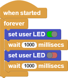
When you press the run button in the MicroBlocks editor, you should now see the built in LED of the student processor blink.
Recap
In this example, we've learned about hat blocks, c-blocks, and command blocks. We used examples of each type of block to control the built in LED of our student processor. The overall structure of this program - a Forever block under a When Started hat - will show up in many MicroBlocks programs for the Gizmo.
The Gizmo Library
In this tutorial, we will introduce the Gizmo block library and the Say block. You will learn how to get input from your gamepad and how to send text back to your computer to help debug your code.
The Say Block
When your Gizmo is connected to a computer, your MicroBlocks programs are able to send information back to your computer. The messages your Gizmo sends will show up in dialog bubbles above the stacks which create them.
The Say block can be found in the Output category of the block palette.

The white bubble in the say block is the message that will be sent to your computer. It can be text, a number, or a value from another block.
You can test the say block by adding a When Started hat block and then snapping a Say block under it with a message of your choice. When you run your program, a bubble with your message should appear above the stack.

Reporter Blocks
We've covered hat blocks, C-blocks, and command blocks in previous chapters. The last type of block we need to introduce are called reporter blocks.
A reporter block looks like a rectangle with rounded corners. These blocks produce values which other blocks can use. Generally, when you have blocks which use values, such as the Say blocks' message, you can drop a reporter block in as the value.
To see this in action, open the Operators category of the block palette and drag an addition block into the Say block's message. Add whatever numbers you want into the addition block and run the program. The stack's output will show the result of the addition.
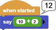
The Gizmo Block Library
There are more blocks built into MicroBlocks beyond the default categories you see in the block palette. The Gizmo block library adds blocks for using Gizmo-specific features. When you connect to a Gizmo from the editor, it should add the Gizmo library to your block palette automatically. If you want to add the library without a Gizmo connected, click the plus button next to "Libraries" in the block palette. Under "Kits and Boards", you'll find the Gizmo library.
The Gizmo library provides command and reporter blocks for
- Using gamepad inputs
- Controlling motors and servos
- Reading ADC ports
- Reading and setting GPIO ports
Logging Gamepad State
Let's put everything we've introduced here together in a program that says whether a button on our Gizmo is being pressed.
To do this, start with a When Started hat block and add a Forever loop block under that.
In the loop, add a Say block and drag a Gamepad Button block from the Gizmo library into the Say block's message. The Gamepad Button block has a dropdown where you can choose which button it will check. Change that dropdown so our program is reading the A button.
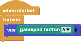
If you run this program, an output bubble will pop up that says "true" when the button is pressed and "false" when it is not.
note
To run this program, you will need the Gizmo to be connected to your driver station. You will need to connect your Gizmo to a battery and turn both the Gizmo and the driver station on.
Recap
In this tutorial, we've introduced the Gizmo block library and the Say block. With these new tools, we wrote our first MicroBlocks program that uses the Gizmo's gamepad.
Spin a Wheel
Let's explore more of the blocks in the Gizmo block library. In this tutorial, we'll cover how to control motors with the Gizmo. For this, we'll make use of a VEX MC-29 motor controller. These motor controllers use a Pulse Width Modulation (PWM) signal to determine direction and magnitude of the motor rotation they control.
The Gizmo Motor and Servo Blocks
The Gizmo block library handles all of the PWM details for you with two command blocks: Set Servo To Position and Set Motor To Speed. Each of these blocks has a drop down menu to pick the Gizmo port and a number input for the position or speed.
The motor block accepts speeds from -100 to 100.

The servo block accepts positions from -90 to 90.

Sweeping Motor Speeds
This example program runs a motor on Gizmo's motor port 1 through the full range of its speeds.
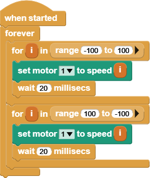
This program begins with a When Started hat block that will run the stack when the program starts running. Underneath that, we have a Forever loop to keep our program running the whole time the Gizmo is powered on.
Within the Forever loop, there are two For loop blocks. This block repeats the stack of blocks within it a specific number of times. It does this by tracking a loop variable, which is named "i" by default. Each time the loop repeats, the loop variable will increase by 1. The input value of the loop block sets the value on which the loop will stop.

note
Unlike most text-based programming languages, MicroBlocks for loops start counting at 1. So, a loop block with end value set to 10 will count 1 through 10 inclusive.
In our case, we've replaced the stopping number with a Range block. This block changes the behavior of the For loop block. With the Range block, we can change the starting point of our for loop. In our example program, we loop through numbers from -100 to 100 in our first For loop, driving the motor from full reverse to full forward. In the second For loop, our range is set up to count in the opposite direction.

The black arrow on the right side of the Range block is a button that will expand the block to show optional inputs. For the Range block, the optional input controls the step size of the loop. For example, if we wanted to count even numbers from 2 to 10, we would want to add 2 to the loop variable for each loop.

In each For loop, we have a Set Motor To Speed block and a Wait Milliseconds block. The motor block will set our motor speed to the value of the loop variable. To use a loop variable as input to another block, you can drag the orange loop variable block from the loop to the block where you want to use it. The wait block is there to give our motor time to react to the new control signal.
To see this program in action, attach a motor to your Gizmo's first motor port using a Vex MC-29 motor controller and run the program. The motor should speed up and slow down over and over, changing directions each time.
note
Motors take a lot of power. Way more than can be safely pulled out of the USB ports on your computer. To run this program, you'll need to have a battery conected to your Gizmo board. Check the instructions around the Main Power Connector for more information on connecting this cable.
Recap
In this tutorial, we learned how to control a motor with the Gizmo block library. We also learned how to use For loop blocks and Range blocks to iterate over a range of numbers. We're just a few steps away from writing code to control our robot with a gamepad, in the next tutorial.
Drive a Robot
In this tutorial, we'll walk through a program which drives a basic robot. The robot this code can control has two motors. Each motor is connected to a wheel on either side of the robot. Our goal is for our program to control each motor with one of the gamepad's joysticks. The left motor should be attached to motor port 1. The right motor should be attached to motor port 3.
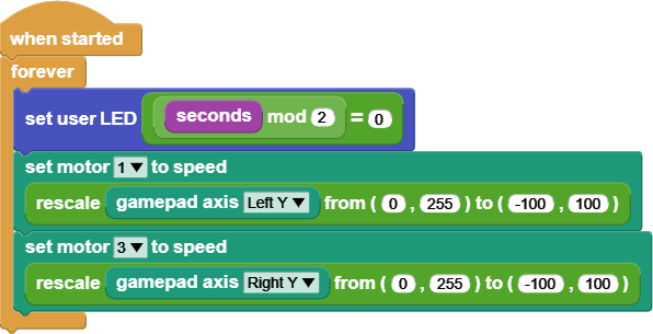
note
To run this program, you will need the Gizmo to be connected to your driver station. You will need to connect your Gizmo to a battery and turn both the Gizmo and the driver station on.
The two control blocks in this program are the When Started and Forever blocks we've seen multiple times in these tutorials. Hopefully, you're familiar now with this pattern to start our program when the Gizmo turns on and keep it running until our Gizmo turns off.
The first thing our program does in the loop is blink the built in LED. This is a useful thing to do in your robot programs so you can tell if your code is still running or has frozen because of some bug in your code. The last time we blinked an LED, we used the Wait Milliseconds block to keep the LED on and off for some time. In this case, we don't want our joystick controls delayed just so our LED can blink. Instead, we'll use the Seconds block and some operators.

The Seconds block is a reporter block that tells our program how many seconds have passed since our program started running. Combining the mod and equality operator blocks lets us check if a number is even. It will return true when the number is even and false otherwise. By turning on the LED when seconds is even and off when seconds is odd, our program blinks the LED slowly enough for us to see.
The next two blocks in our loop stack are motor blocks. In this case, we are setting the motor speed using the position of the left and right vertical joystick axes. The joysticks give us their position on a scale of 0 to 255, but our motors take speeds in the range -100 to 100. To translate from the joystick range to the motor range, we use the Rescale block.

The Rescale block has five input fields. The first is the value that will be scaled. In our program, we've filled this input with the Gamepad Axis block. The second and third inputs of the Rescale block tell the block about the input value's range. The fourth and fifth inputs define the output range.
The Rescale block is considered an advanced block in MicroBlocks. In order to find it, you need to go into the settings menu and click "show advanced blocks." After that, it should show up in the Operators category of the block palette.
So, using the Rescale blocks in our program, a joystick value of 0 is transformed into a motor speed of -100. A joystick value of 255 becomes a motor speed of 100. Any joystick position between those is mapped to the corresponding number in the output range.
Recap
In this tutorial, we built a program to drive a basic robot. You can use this program as a starting point for your robot's code.
If you would like an example program that includes more motors and servos, check out the BEST default program. You can find this by clicking "open" in the file menu and opening "BEST Robotics Default Program" from the "Kits and Boards" category in the examples pop up.
Troubleshooting
Sometimes things break. Before you decide to get help, there are some troubleshooting steps you can take on your own. This section details those steps.
Driver Station
The driver station has a handful of failure modes and things that can break it. Here's some common failure modes and issues.
Getting Logs
The Driver's Station prints out logs to its HDMI port. You can connect this to a monitor and the logs will be displayed. The content of these logs requires pretty deep knowledge to understand, but you may be asked to provide a picture of the Gizmo logs during debugging.
The system processor provides an event stream over its USB port when accessed as a serial port. The Gizmo will stream data at 9600,8,n,1 that will tell you what event its currently processing. This information can be useful in forming a bug report to tell what the Gizmo is trying to do at the time of encountering a bug.
Imaging Issues
During imaging you may encounter issues where Balena Etcher does not write the full image. This can usually be resolved by restarting the imaging process, disconnecting and reconnecting the micro SD card from the reader, or using a downloaded copy of the .img file rather than the URL.
Boot Issues
If you encounter issues with booting the Gizmo DS make sure that you have supplied a gsscfg.json file as described in the setup guide.
Under rare circumstances the micro SD card can become corrupted. If this occurs you must re-image the micro SD card.
Binding Issues
The binding process relies on passing information back and forth between the Gizmo and the driver station. After pressing the system processor BOOTSEL button it may take up to 1 minute to complete binding. If the Gizmo has not bound within this interval, reboot both the driver's station and the Gizmo to try again.
FMS
The FMS is made up of multiple systems. These can each encounter unique failure modes, this page lists some of the common ones and steps to recover from each.
Flash Device Failure
During device flashing, you may get a key refused message, or other error from the flash process. If this occurs, re-run the flash-device command without rebooting the device you are flashing.
Bootstrap Failure
Most bootstrap issues arise from not waiting long enough for the network devices to boot. This is a process that requires patience. If you find that you have started the bootstrap too early and the process has crashed, you can clear out the state and restart it:
$ rm -r ~/.netstate
Note that doing this after the network configuration is actually done will result in an unrecoverable situation where you need to re-flash your equipment and re-bootstrap.
Bootstrap Terraform Initialization Fault
If the bootstrap process fails with a message related to terraform provider initialization, check that the FMS Workstation is still connected to the internet via WiFi. This connection must be maintained until the FMS network is fully configured and connected to wired internet.
Field Remap Aborted
If you try to remap the location bindings for teams while another remap is in progress the system may abort both. If this occurs, retry the binding and the new attempt will succeed.
Gizmo
The Gizmo itself is relatively straightforward, but does occasionally encounter trouble. Before going deeper into any of these steps, try turning off the Gizmo and turning it on again.
What do the lights mean?
There are 2 main groups of indicators on the board. There are static indicators which show which systems on the Gizmo have power, and there are color changing indicators that show specific status.
Power Status Indicators
There are 7 power indicator lamps which are distinct colors. From top to bottom these lights indicate:
- Main Power
- Pico Power
- GPIO Power
- Servo Power
- Motor Bank A
- Motor Bank B
- Student NeoPixel Power
Dynamic Status Indicators
Below the power indicator lamps, there are 3 dynamic indicator lamps that change colors. These indicate from top to bottom:
- Network
- Field
- Battery
Here's a handy graphic that helps explain what the different combinations mean:
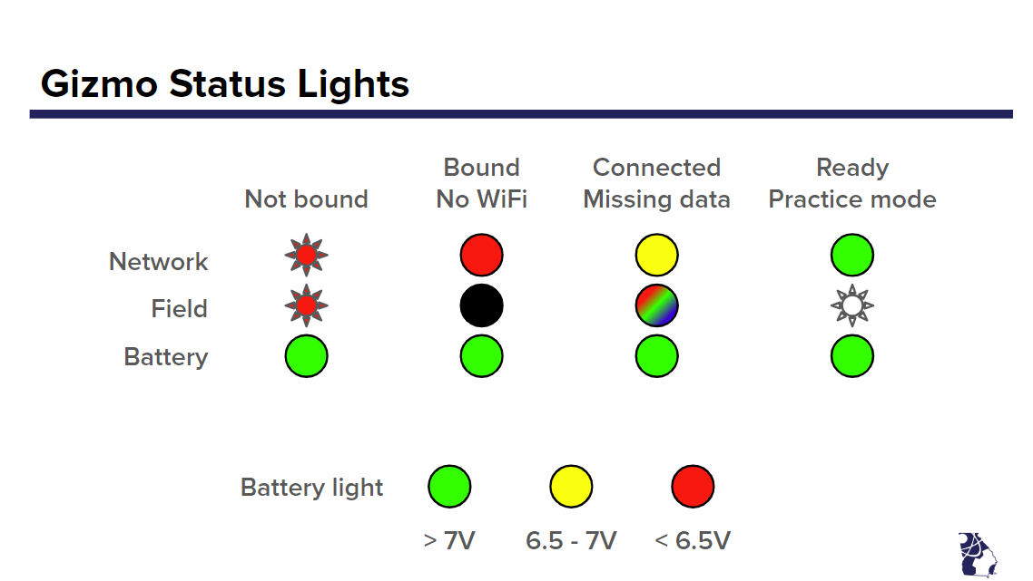
Serial Event Log
If you can't determine what the Gizmo is doing from the lights, you can connect a USB cable to the system processor. It will present itself as a serial port which will stream an event log at 9600,8,n,1. The messages in this log provide useful debugging information and you may be asked to provide this information when opening a problem report.
If you do not already have a serial terminal available, Google Chrome can serve this function with the aid of this site.
Appendix
Welcome to the Appendix! This section contains information that isn't really suited to go in any other section.
Writing Images
Configuring some parts of the Gizmo ecosystem involve writing entire disk images all at once. This requires tooling that can deal with these image files, and this page details information on the options available and how to use Balena Etcher, a good choice for beginners.
To write an image to an SD card, you have a few choices. If you're on a mac or a Linux machine, you can use dd. On Windows you can use Win32DiskImager. If you've never written disk images before, the Gizmo team recommends you use Balena Etcher which is available for all platforms, and guides you through the process.
tip
Balena Etcher Portable edition can be used without needing to install. This can be convenient to not clutter your machine with extraneous programs, or to write files from a machine where you do not have administrative permissions to install new programs.
Writing software images with Balena Etcher looks like this:
When you open the main application screen, it will look like this:
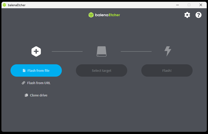
Either download and extract the required image file, or paste the URL directly into the box on the "Use Image URL" screen:
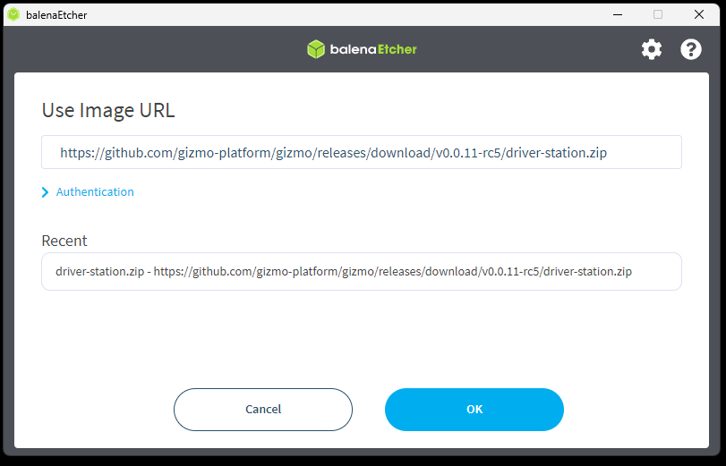
Click the "Select target" button and connect your micro SD card. The disk will appear as a target that you can use.
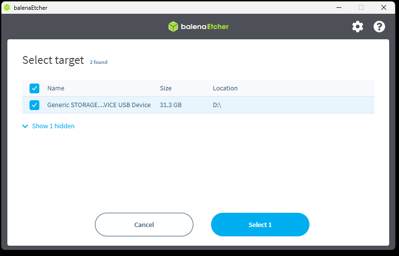
warning
Balena will automatically hide any volumes that it detects the system may be booted from, so generally you can't hurt your computer with this process. Be extremely careful though to select the right disk if you show hidden devices. A good way to make sure you've got the right disk is to confirm the size of the device, which should match closely to the size of your micro SD card. The exact size may differ slightly due to the way in which device manufacturers market capacity.
Once configured, the Etcher window will look similar to this:
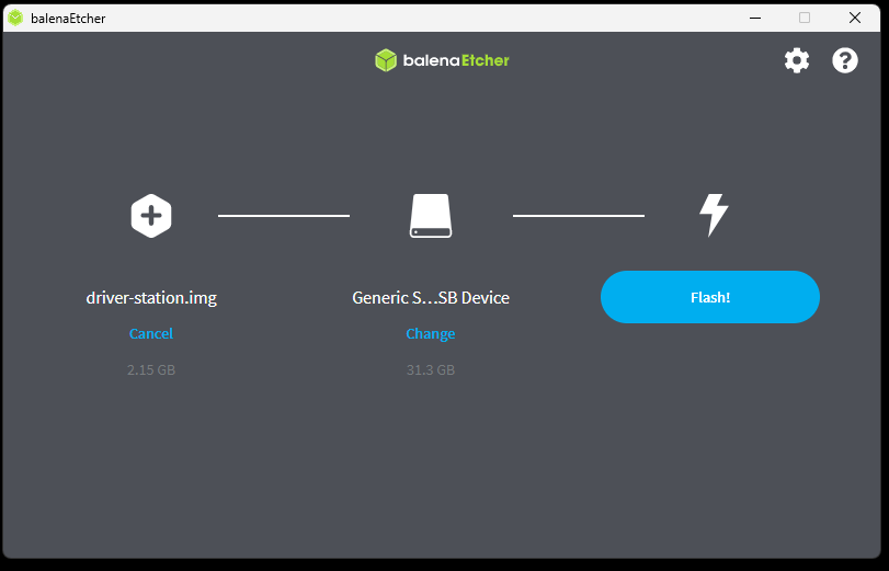
The flashing process will take several minutes. On average with a modern computer, the Gizmo team observes this process taking about 3 minutes.
note
You may be prompted to authorize the command prompt prior to the flash process commencing, this is a normal prompt as Balena Etcher needs to access low-level system utilities to write the data to the micro SD card.
Once complete, the Etcher window will look like this:
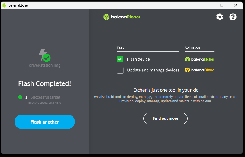
You may now close Etcher and remove the micro SD card.
Fully Repartitioning Disks
Under certain circumstances, it may be necessary to completely reformat disks. This should not ever be necessary for the FMS as it is a fully self-contained system image, however the driver station disks have very strict format requirements which can be corrupted by certain automated Windows processes. This page includes instructions for Windows. If you'd like to contribute a guide for macOS, please feel free to contribute!
Microsoft Windows
Fully repartitioning a disk on Windows is performed using an elevated Command Prompt or PowerShell. In the start menu, type "PowerShell" and then click the option to "Run as Administrator". Authenticate when prompted, and you will be greeted with an administrative command prompt.
danger
Take care when working with an administrative command prompt, and doubly so when working with disks. It is possible to erase system disks or corrupt other data while following this procedure if you do not pay attention and select the disk you think you're selecting.
Ensure the micro SD card you wish to partition is plugged in and launch diskpart in the PowerShell window.
Obtain a listing of disks by typing list disk. The output will look similar to this:
DISKPART> list disk

  Disk ###  Status         Size     Free     Dyn  Gpt
  --------  -------------  -------  -------  ---  ---
  Disk 0    Online          232 GB  1024 KB        *
  Disk 1    Online           28 GB      0 B        *
Note the * mark in the GPT column on Disk 1. Disk 1 is the micro SD card in this example, and has been identified as a GPT disk. GPT disks are a more advanced format for disk partitions that do not work with the Driver's Station ROM, so this disk must be repartitioned. Disk 1 was identified as the micro SD card because its size matches the size of the expected disk, which was a 32GB card.
note
The disk shown above says it has a size of 28GB but the label physically on the disk identifies it as 32GB. This is normal as most drive manufacturers market capacity using powers of 10, whereas drive capacity is actually measured in powers of 2. This results in a disparity between the labelled capacity and the actual capacity. The actual capacity will always be slightly less than the labelled capacity.
Select disk 1 and remove all data from the disk. This action is immediate and cannot practically be undone, so be sure you are selecting the right disk!
DISKPART> select disk 1

Disk 1 is now the selected disk.

DISKPART> clean

DiskPart succeeded in cleaning the disk.
Create a new partition table using MBR format, create a new partition using the entire drive, and finally mark it as active.
DISKPART> convert mbr

DiskPart successfully converted the selected disk to MBR format.

DISKPART> create partition primary

DiskPart succeeded in creating the specified partition.

DISKPART> active

DiskPart marked the current partition as active.
Finally, format the new partition as a FAT32 volume. If formatting for a driver's station, make sure you set the volume label to include the team number. In this example, this particular Gizmo Driver's Station is being prepared for team #228.
DISKPART> format fs=FAT32 label=GIZMO228 quick

  100 percent completed

DiskPart successfully formatted the volume.

DISKPART> exit

Leaving DiskPart...
Getting Help
While this manual aims to provide you with information about how to get started, resources to learn more, and pointers to additional sources of information, its entirely possible that you will encounter a problem that you need help to solve. Recognizing that a problem is beyond your current skill level and seeking advice is the first step on the path to being an expert in a topic.
There are several places that you can get help for components of the Gizmo ecosystem. Before you head off to these places, however, please take a moment to review the information below on asking good questions.
-
Don't ask an XY Problem. When you get stuck, its really easy to get stuck in the thought process of "If I could only figure out how to do X I could achieve Y." This kind of thinking can lead to asking questions about X that are totally unrelated to Y. When you ask a question, try to provide a clear description of what you want to achieve, not how you think you'll achieve it.
-
Clearly describe what you've tried so far. There's a reason most technical support conversations start with asking if you've tried turning it off and back on again. Simple solutions can fix a myriad of problems, so be sure to try some basic troubleshooting steps on your own first (check batteries, verify software, etc). When you ask your questions, this will help those answering to not waste your time with things you've already tried.
-
Describe the setup of your environment and your configuration. For hardware problems this is going to include at minimum a description of the exact fault. The problem is never "it doesn't work" its always going to be more specific such as "a motor controller connected to port 2 doesn't seem to be able to go into reverse." For software problems, be sure to include information about the versions you have installed, your operating system, code that you're trying to make work if applicable, and anything unusual not described in this manual that you may be trying. Its also a good idea to see if you can replicate the problem in different configurations (does an earlier version of your program work, does it work on another computer, etc).
-
Ask your questions to the right people for the right problems. The Gizmo platform is made up of some custom components and a large number of Open Source components. While the Gizmo team is happy to read any problems you send, we may need to point you to a more appropriate forum where other experts can provide you with more specialized help and support. The sections below will describe the kinds of problems that you may encounter and where you'll get the best support.
Gizmo Specific Problems
Gizmo specific problems are, we hope, extremely rare. However just like the rare sighting of a black swan, they do occur. Problems that are specific to the Gizmo platform include anything physically wrong with a controller, any issues with the driver's console, and problems with the gizmo tool. For problems with the Gizmo itself, we make use of GitHub Discussions which provides a forum experience. You can seek help in our forum here. Don't worry if you don't know what category to post into, our team can always move the thread if it fits better in a different category.
Gizmo FMS Problems
Gizmo FMS problems are specific to the control and network layers of a Gizmo enabled Field Management System (FMS). If you are running a competition, you will have been provided specific contact information to use to receive real-time support with the FMS. If you are planning to run a competition and wish to engage this level of support, reach out in the Gizmo forums above and we'll get you in touch with the right people.
Arduino IDE and Arduino Code
For issues with the Arduino experience that are not related to the Gizmo library you may wish to go directly to the Arduino site. There you'll find documentation on the Arduino IDE, the language specificiation, all libraries that are available, as well as information about the Arduino Forum and Discord chat where you can talk to other people using Arduino to get help, advice, or even just to learn from other projects people have built.
Circuit Python
If you are programming your Gizmo with Circuit Python, a wealth of knowledge and resources exist on the main Circuit Python website. From this site you can use the forums, join the Discord, or read tutorials that will expand your understanding of the Circuit Python environment.
Glossary of Terms
This glossary contains a selection of terms that are either unique to the Gizmo platform, or are used in specific contexts within the Gizmo ecosystem.
Arduino
Arduino is a platform and ecosystem of microcontrollers, libraries, and resources that make embedded control systems approachable and easier to use.
Library (Software)
A software library is a re-usable module of code. Libraries can be developed by compartmentalizing part of a larger program, or obtained from a 3rd party such as a hardware manufacturer or software vendor.
Mechatronics
Systems that contain both mechanical and electrical systems, such as a robot.
Microcontroller
A microcontroller is a kind of very small computer. These computers run simple programs that take inputs, perform comparisons and computations and then export the results as outputs via devices such as lights, servos, and motor controllers.